Hi I want to ask, I am trying to receive data from a CAS CI-200SC digital scale Manual Owner with Arduino Mega using RS232 to ttl MAX3232 with serial hardware. This is the code I used for testing.
are you sure your TTL-RS232 module is working
do a simple loopback test, e.g.
// Arduino Mega serial1 test

// mega Serial1 pin 18 is TX1
//      Serial1 pin 19 is RX1
// for loopback test connect pin 18 to pin 19

// for RS232 shield connect
// Mega pin 18 TX1 to TTL/RS232 Tx
// Mega pin 19 RX1 to TTL/RS232 Rx
// for loopback test connect 9-pin D_type connector pins 2 Tx to 3 Rx (pin 5 is GND)
// connect GND pins together and VCC to 5V

void setup() {
  Serial.begin(115200);     // initialise serial monitor port
  Serial1.begin(9600);//115200);    // initialise Serial1
  Serial.write("Arduino Mega Serial1 test -  for loopback test connect pin 18 to pin 19\n");
  Serial.write("RS232: Mega pin 18 TX1 to TTL/RS232 Tx and pin 19 RX1 to TTL/RS232 Rx\n");
  Serial.write("RS232 - loopback connect 9-pin D-type pin 2 Tx to pin 3 Rx\n");
}


void loop() {
  if (Serial1.available()) {  // read from Serial1 output to Serial
    Serial.write(Serial1.read());
  }
  if (Serial.available()) {  // read from Serial outut to Serial1
    char inByte = Serial.read();
    //Serial.write(inByte);     // local echo if required
    Serial1.write(inByte);
  }
}
how to test it? is it after uploading the program to the arduino then immediately connect the db9 pins 2 and 3 and wait in the serial monitor? sorry I'm a beginner in this section.
just tested on a Mega and my original code post 2 had them the wrong way around (in fact I had a Mega in which pins 18 and 19 were labled the wrong way around) - code now correct
the following worked when I connected D-type pins 2 and 3 for the loopback test
// for RS232 shield connect
// Mega pin 18 RX1 to TTL/RS232 Tx
// Mega pin 19 TX1 to TTL/RS232 Rx
you can check which are the TX and Rx lines
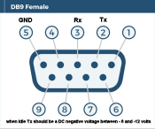
e.g. on my TTL-RS232 module not connected to anything in idle (no transmission)
pin 2 Tx is -9volts
pin 3 Rx is 0volts
if you check the scale the TX pin should be between -8 and -12 volts and the RX pin 0volts
you then connect
RS232 Tx pin 2 to scale Rx
RS232 Rx pin 3 to scale Tx
connect GNDs together (D-type pin 5)
this photo shows a Mega/RS232 module connected to a Quectel ES21 modem (note pins 2 and 3 interconnections)
that shows the Mega <> TTL_RS232 module connection is operational
you can now connect it to the scale with some confidence that part of the system is OK
did you try checking the voltages of the scale RS232 wires when not connected to anything?
the TX line should be -8 to -12 volts if the connection is idle
if both are female D-type 9 pin connections the typical connection would be
TTL-RS232 pin 2 Tx to scale RS232 pin 3 Rx
TTL-RS232 pin 3 Rx to scale RS232 pin 2 Tx
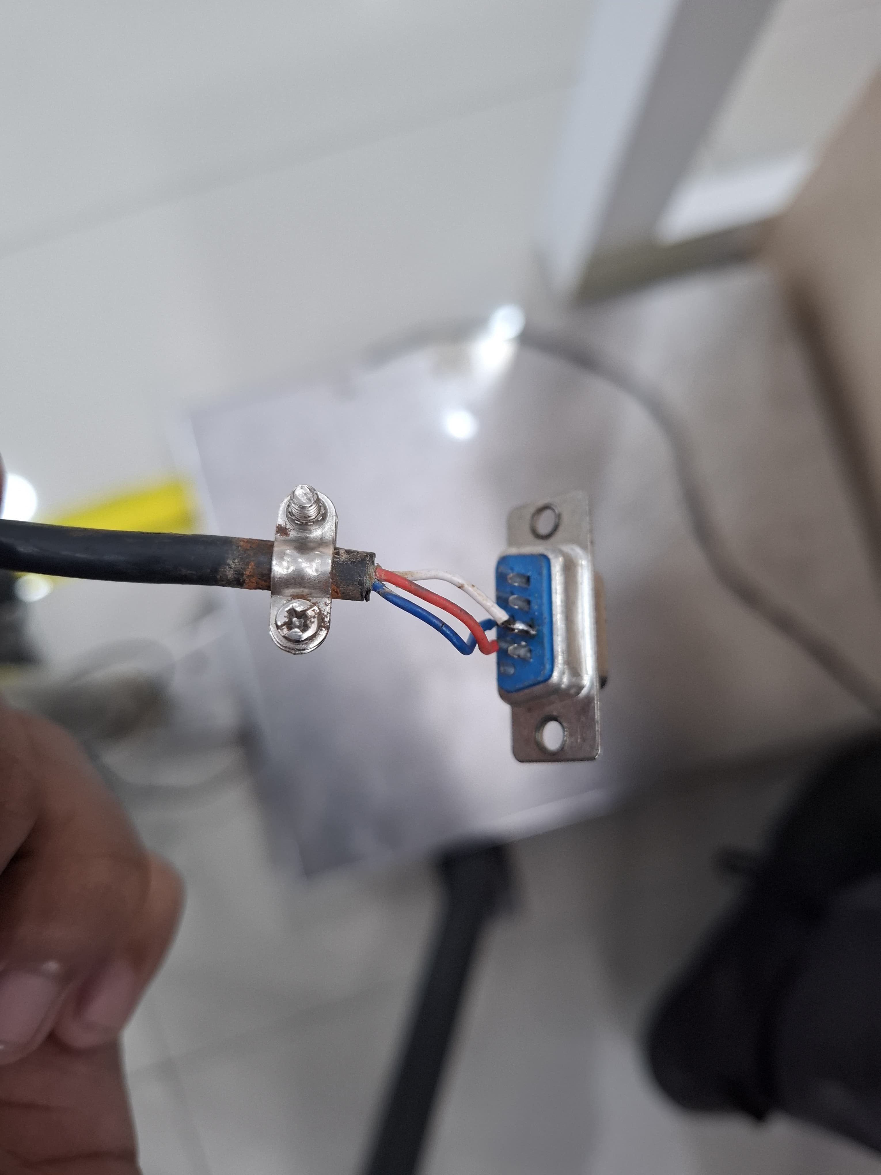
Is there usually only 3 cables for RS232 on CAS CI-200CS digital scales? I tried to disassemble the DB9 connector belonging to the scale and there are only 3 connected to pins number 2, 3 and 7.
According to the CI200 Series owner's manual, pins 2, 3, and 7 are correct for the scale end of the cable. Pin 2 is Tx, 3 is Rx, and 7 is GND.
What type connector is on the other end of the cable?
For the other end I use MAX3232 with db9 female connector. Previously the digital scale db9 connector was damaged and replaced with a new one so I tried to see the wiring in the db9 connector and the results were as shown in the picture in post 15. What I know is that pin 7 on RS232 is used for RTS and GND is on pin 5, so I am a little confused whether the wiring above is correct or wrong. I am still a beginner in this RS232.
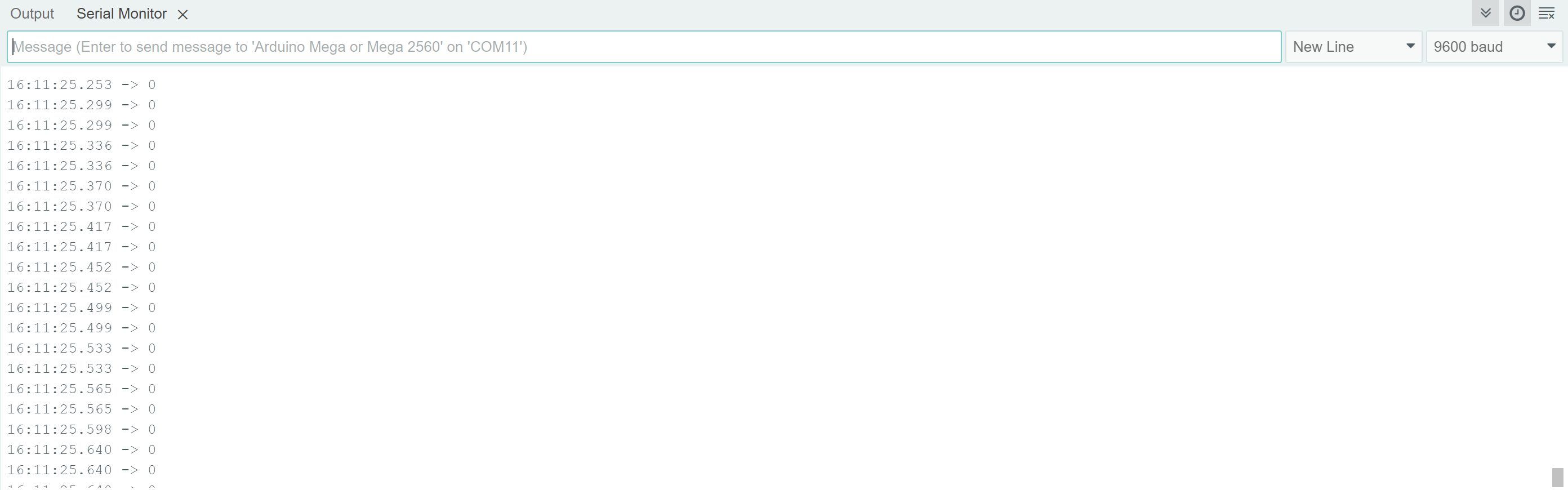
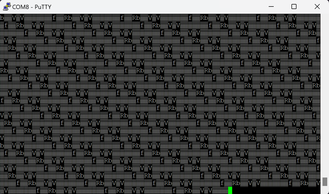
Are you certain of the settings for baud rate, number of data bits, and parity bit? There is definitely a pattern in the putty output, that appears to repeat in a 17-character sequence.