I have a good Fluke meter, and actually a DS203 oscilloscope that I have used once on a project. Would it be able to test the PWM waveform? It’s pretty basic, but it does have 2 channels. I’m fairly fluent in some aspects of electronics, but not using an oscilloscope. So if it’s out of my league that’s ok. If it’s something I could do, I’d enjoy learning about it. If you knew of some good tutorials on how to test the mosfet with one, I’m buying extra mosfets for the ones I accidentally smoke. LOL
- Probably okay for this.
- Sounds like you are on the right track !

Your big lithium battery could probably do a 1000 amps for 30 seconds before exploding if there was a short circuit. Please be sure to have a fuse as close to the battery as possible. 30A if that's the most for your motor. When starting the motor, start with a low pulse width to avoid high current when starting. You should start using your scope just on a signal generator at first so that you get to know the controls and triggering to lock the waveform. Once you have mastered it you will find it very useful
Thanks. I got a 60A battery post fuse.
I think I’ll have some spare time that I’d like to learn about testing that mosfet with my scope.
Well, I think this MOSFET stuff and MOSFET drivers are a tad over my head.
Using the circuit I showed in post #8, if works. Kinda.
with the MOSFET gate just set to high from my arduino, the Vds, or the reading with my Fluke meter across source and drain is 0.00 Which is good I think.
Then I tested the PWM with a tiny motor, and a POT to adjust the speed, and it all works good.
Next, with a bigger motor drawing more amps, it also runs ok, IF I keep the arduino's PWM low at default setting. (1K or 500hz). But the motor whines very much at that low hz. I set it to 20Khz which is the normal I use, and now I get heat issues. The MOSFET will run continuously without heating up if I run it wide open. At about 75% speed it gets warm but doesn't over heat, but much lower speed than that and the heat runs away with it pretty quickly so I can't touch it anymore. Also, turning on the motor, it no longer responds to the low PWM levels, it's only once my POT knob gets turned about 3/4th of the way up that the motor starts turning.
Is this something to do with capacitance levels on the gate as it turns on/off? I'm just bread boarding it all now, and the finished project will have a custom PCB with short, large traces on the high amp parts of the circuit.
I have a pocket Oscilloscope, is there a way to check the gate turning on/off? Here's a photo of how things are 'rigged'.

-
This definitely says the MOSFET is staying too long in the linear region, not switching properly.
-
It would help to see a scope image of the 20kHz drain to source waveform.
-
Suggest you place a fuse, of appropriate size, on the battery positive lead.
-
Is you out board motor controlled by an internal electronic control circuit inside this motor ?

-
Suggest you place a fuse, of appropriate size, on the battery positive lead.
-
it's there, as seen in that photo.
-
Is you out board motor controlled by an internal electronic control circuit inside this motor ?
-
No circuitry in this one. Speed is set to high which is a direct connection to the motor. (Other lower settings use resistors to burn away excess energy)
Here's a Drain source photo. This is PWM set via:
TCCR1B = TCCR1B & B11111000 | B00000001; // set timer 1 divisor to 1 for PWM frequency of 31372.55 Hz
AND
I only have a small gear motor hooked up to it that's currently running at half speed - analogWrite(128). I just fiddled with the scope buttons til I got something that looks half way readable. Would I need to hook my large motor up to get a different reading on the scope?

Hmm. I don't know very much about this, but this looks helpful to someone who can read this scope:
Here's a screen shot of the big motor running, I had to adjust the settings to get of time, etc, to get this to fit on the hold screen.
Again, this was taken at 31Khz, about half speed. I couldn't leave it run very long as it over heats...
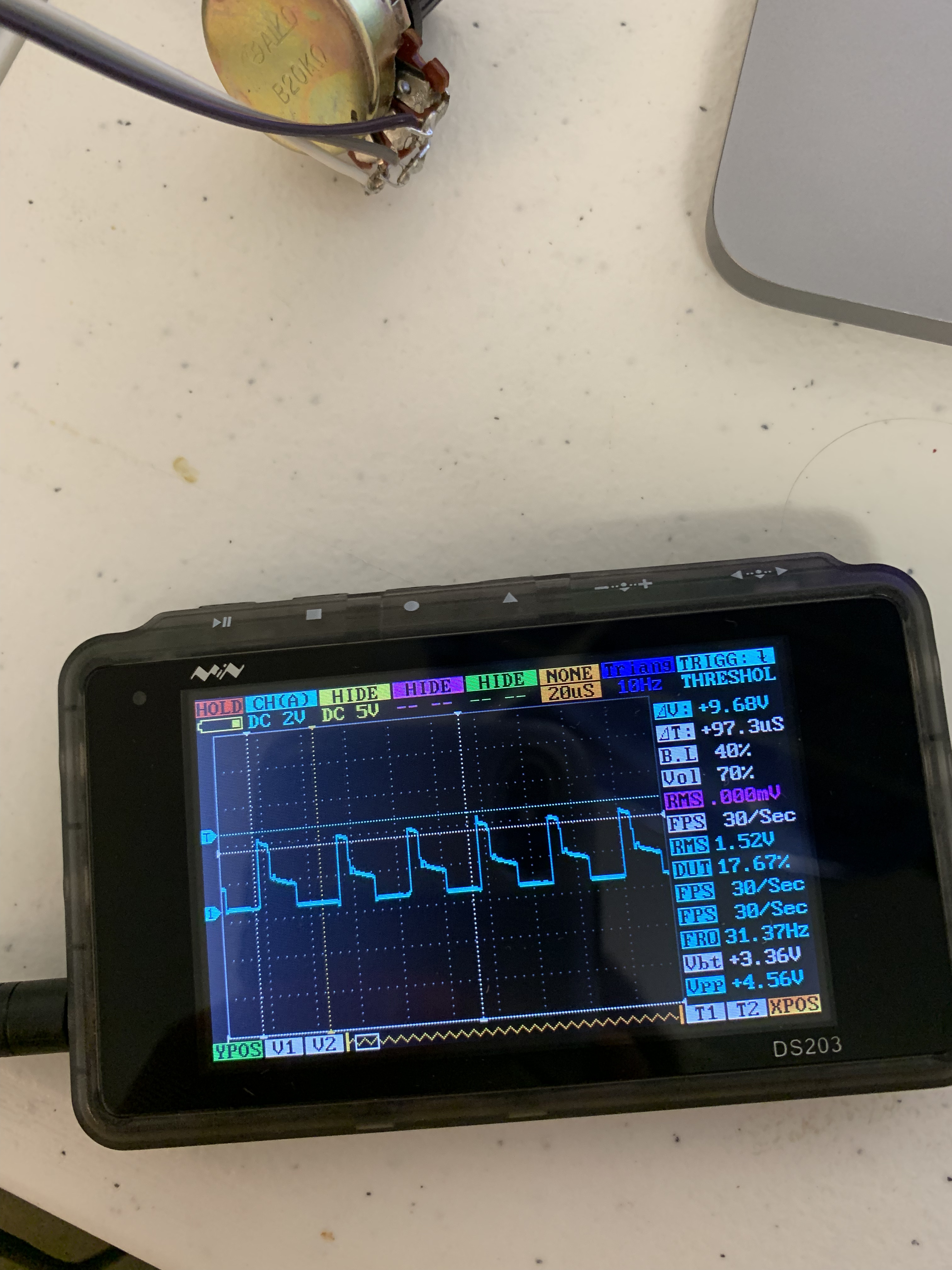
In my limited capacity of knowledge, it looks like the MOSFET turns on quickly, the kinda fall back off considerably. Shouldn't it be more like a square wave? I have no idea what the problem is that would cause this, though...
Here's a video showing the PWM value, starting at max (255), and as I turn the POT down, it slows down, and you can see the scope with it. The trolling motor stops moving, when the PWM value gets down to about 200.
Please add the gate signal as the second channel.
-
The red line says the MOSFET is fully turning ON, good.
-
The overshoot ringing (green) which is probably larger, but due to test equipment capability, is about 6v. This is concerning.
Probably as a result gate long wires and circuit capacitance. -
MOSFET OFF voltage (blue) is very LOW probably because your wire gauge is too small.


Oh! I just realized I hadn’t put that big flyback diode across the motor. Maybe there’s some kind of EMF feeding back from the motor due to a lack of that diode? I will do that later tonight.
WOW! well, there's still a lot I don't understand about this, but I know it will work! After adding that flyback diode across the motor, is works like a charm! I can PWM it at any speed, and the mosfet doesn't even get warm! I'm really amazed. Though it's not under load, so the amps be only be 6 or 8 instead of 15 or 25, but I think I'll move forward with moving this all onto a PCB with proper and short traces...
I was wondering about using the second scope probe to match the gate voltage with the drain voltage. I'll post what I find. May be tomorrow.
thanks,
-
Without the kickback diode, high kick back voltages and ringing makes the MOSFET stay in the linear region.
The MOSFET can in fact be destroyed due to the high Vds. -
We want the MOSFET to be either fully ON or fully OFF.
We can determine how much power a component dissipates by multiplying the voltage across it by the current flowing through it.
Example,
-if Vds is 0V (MOSFET fully ON) and current was 10 amps, Watts = 0V * 10A = 0 watts.
-if Vds is 10V (MOSFET fully OFF) current will be 0 amps, Watts = 10V * 0A = 0 watts.
-if Vds is 5V (MOSFET 1/2 ON) and current was 10A, Watts = 5V * 10A = 50 watts, HOT.
my motor is currently running fine at any speed, although I tested the amperage it's drawing and it's only 3 amps, as it's not doing any work yet. The MOSFET stays cold.
In this photo Ch A is connected to the Drain, grounded on the source (GND),
Ch B is connected to the Gate, also grounded on the source (GND).
I don't understand why I have to have chA voltage set on 2V, and ChB on 10V, to get visual reading on the screen. But I'm self taught on using a scope, and this Chinese one has no real manual.

-
A 10V to 0V waveform (yellow from gate driver) Vgs should be just that 10V to 0V.
-
A waveform of V(motor-supply) to 0V is our goal output signal at Vds, i.e. with little or no ringing.
If the motor supply was 10V we want to see an output waveform of 10V to 0V, full OFF to full ON. -
Your blue trace, 2v per division, needs to be evaluated more, show us your current schematic and your current sketch. This shows about 1V, too low.

-
BTW, start getting into the habit of placing a channel trace on a major vertical line so we can make proper readings.
-
Time to change your batteries.
Do your probes have a X1/X10 switch on them?
It looks to me as though the blue trace (channel A) has a X10 probe attached, so that the sensitivity is really 10 x 2V = 20V per division.
If the yellow trace has a X1 probe attached, then the sensitivity would be 10V per division (as indicated).
That would explain why the yellow trace is roughly twice as large as the blue trace.
There is a manual for the DS203 oscilloscope here.
(I think it's the same as yours).
