Wawa:
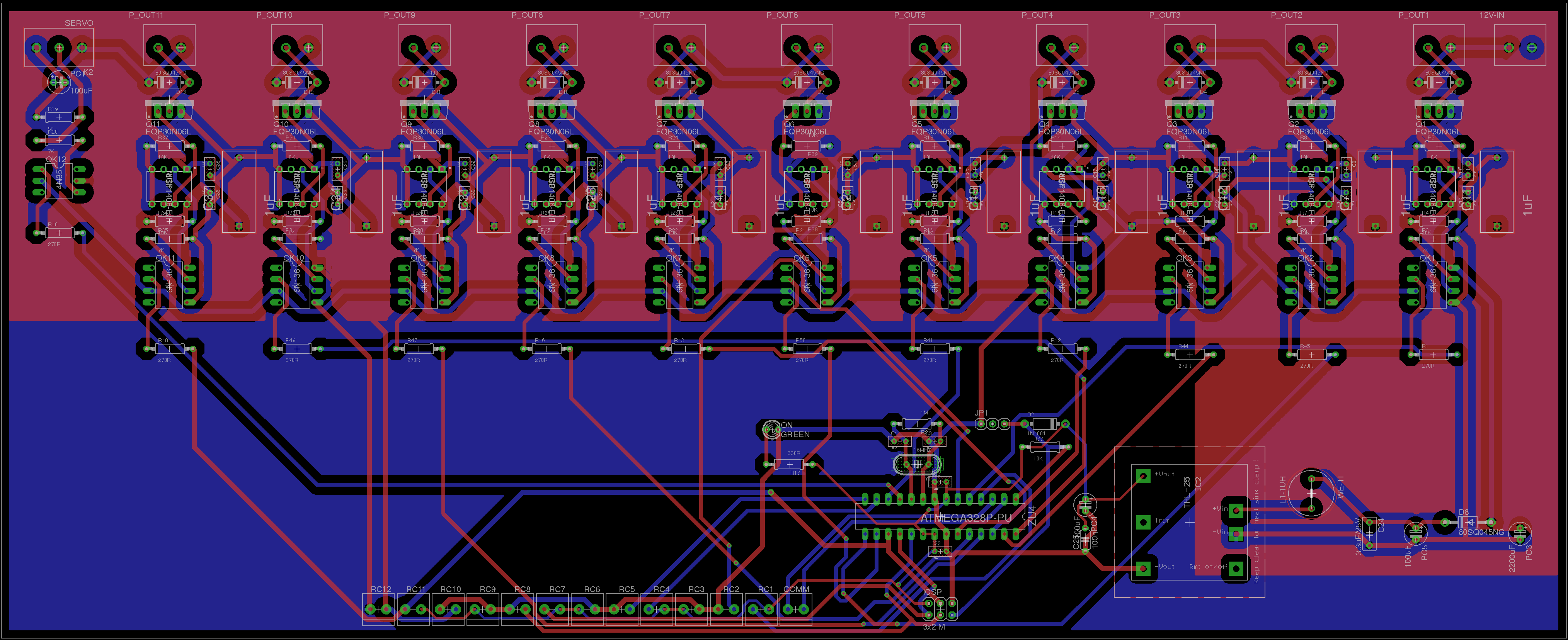
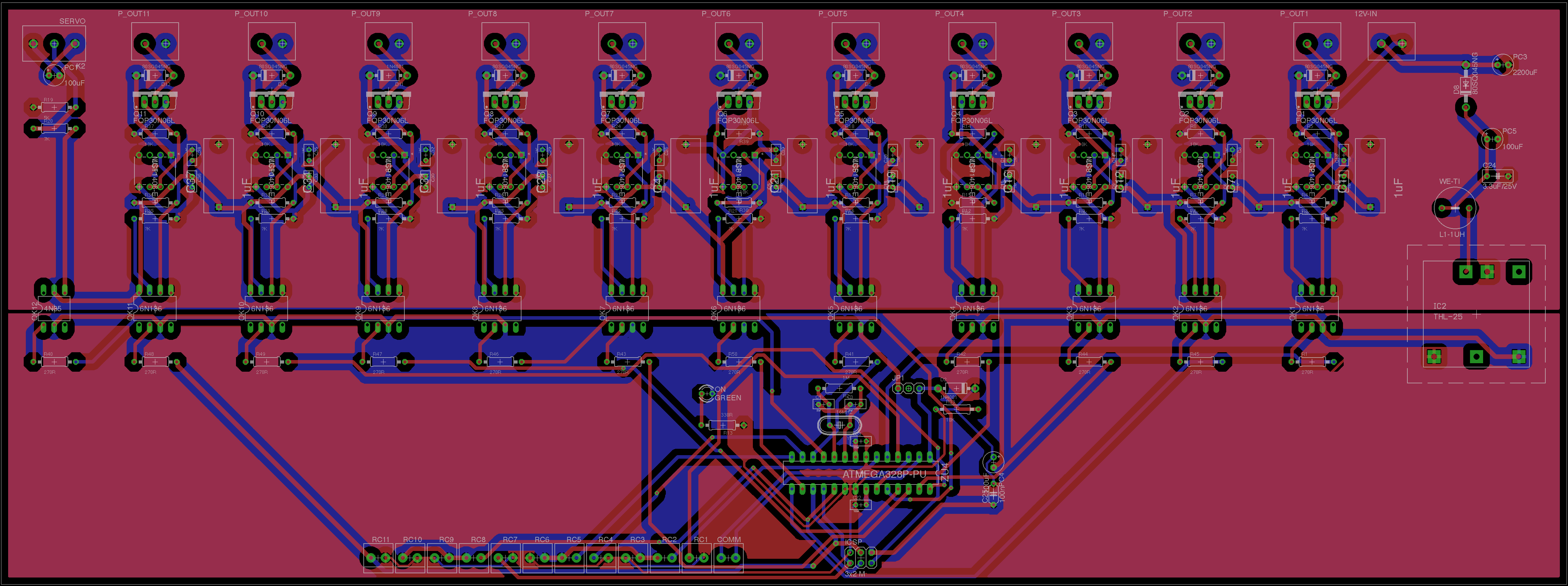
I think the biggest problem with your board is the layout.
Ground and supply take large detours. Not good when solenoid currents mix with MCU supply currents.
Why the heatsinks. I thought this was for 1Amp solenoids.
Seems silly to use big heatsinks (for power) and thin tracks (not for power).
Leo..
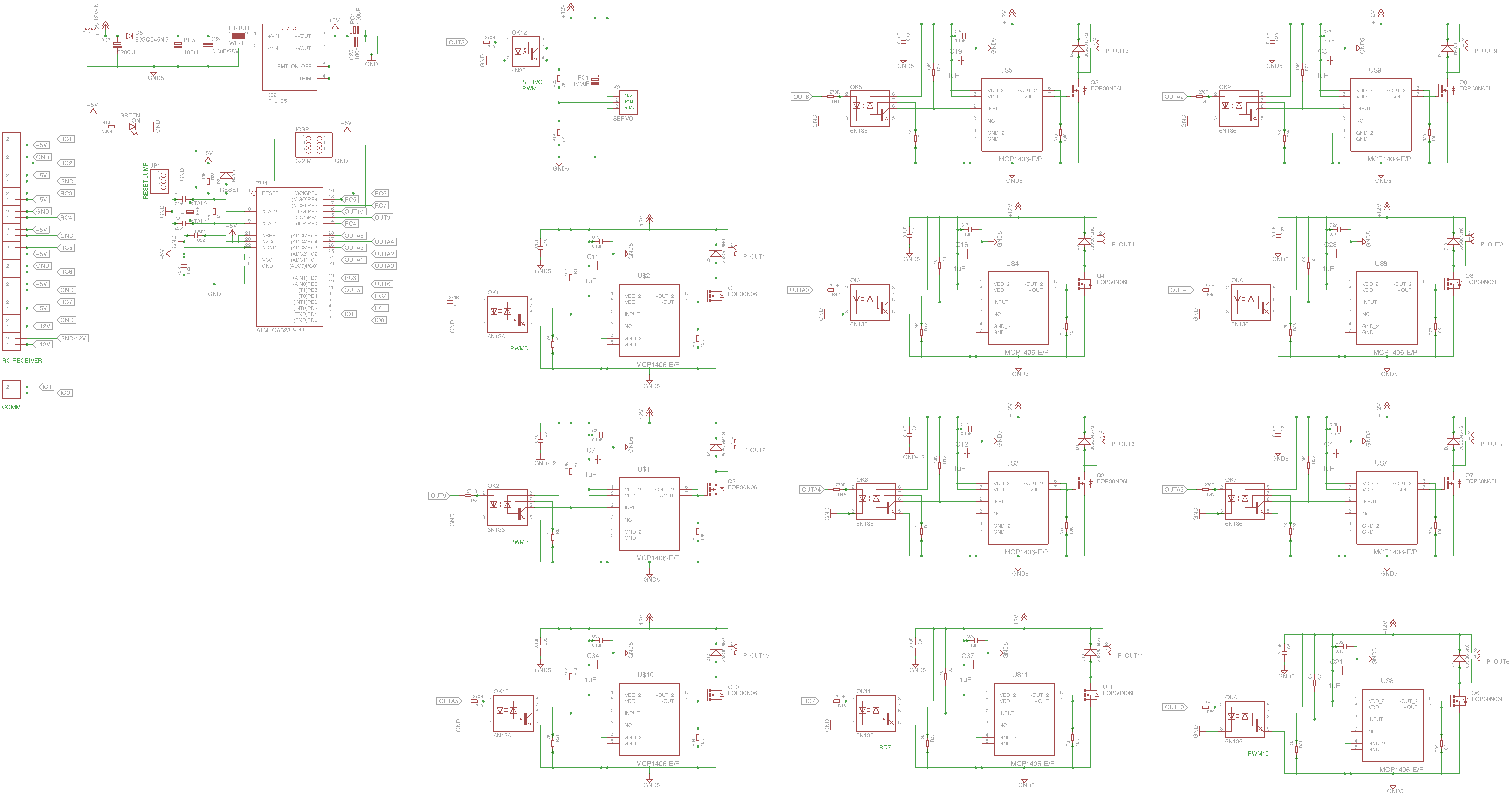
I'm posting here my schematics and my board layout.
I'm beginner and this is my first attempt to design a board layout, so I'm sorry if I did mistakes.
The main power is 12V coming from a 12V/200Ah AGM battery and I use an isolated power supply to power the atmega328p; I also uso optoisolators to drive the MOSFETs.
The solenoids are rated 12V,2A.
I placed a ground plane for the 12V and a power plane for 12V, too.
I don't know if I need to place a ground plane also the 5V.
May be I won't need it since the atmega328p circuit is already isolated from noise.
I've read in the atmega328p guidelines that it is useful to put a ground plane near the oscillator.
Do you think I need it?
It would be best to have separate boards for the ATMega and mosfets. Then you could have far more isolation betwen your 12V and 5V. Just use a ribbon cable orCAT5 cable.
With the exception of the weird traces directly under some of the optocouplers, that isolation looks good for at least a thousand volts. You could be switching mains currents and have the substation get hit by lightning and the low voltage side of the board will probably survive.
For 12V and 5V, that looks perfectly fine. Unless the 12V wires go a long distance outdoors or into a cabinet with mains power.
One tip: don't run your traces so close to the pads. Give them a little more space so the ground pours can flow around the pads. It actually doesn't seem to matter too much in your design - the pours seem to get almost everywhere - but if you're using a pour then it is always good to give the current more paths to flow around as if it was a solid layer.
Twisting the solenoid wires into pairs is a good idea.


