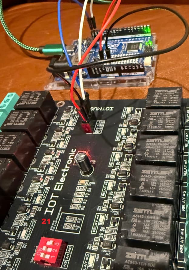
Goal: Build program where I can control 4 x 16 channel relay boards. Starting with two
Connected to USB Laptop -> I can push program but no response from board
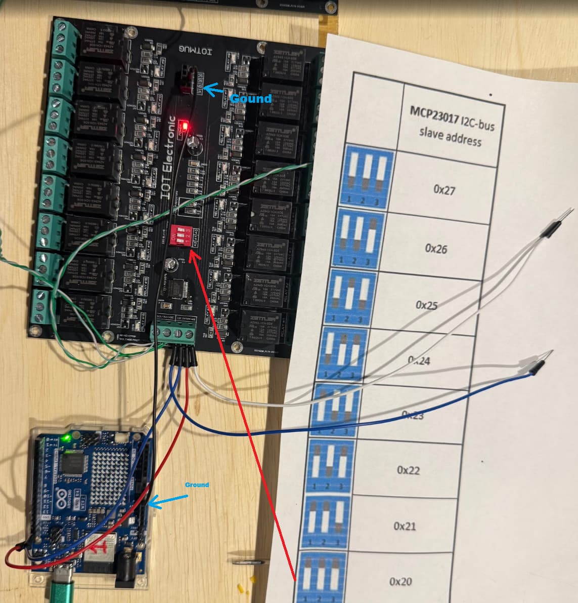
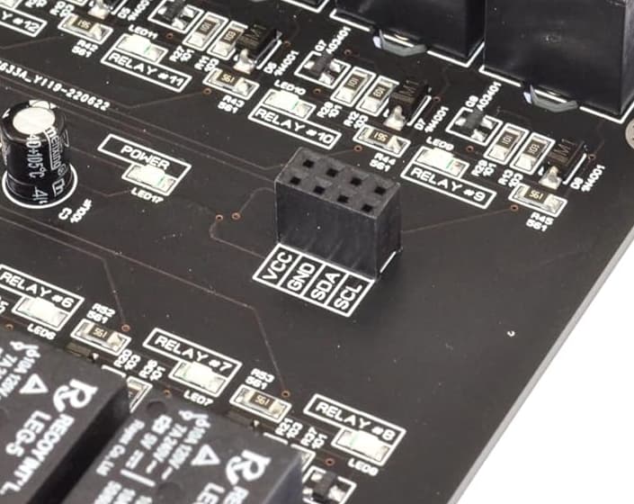
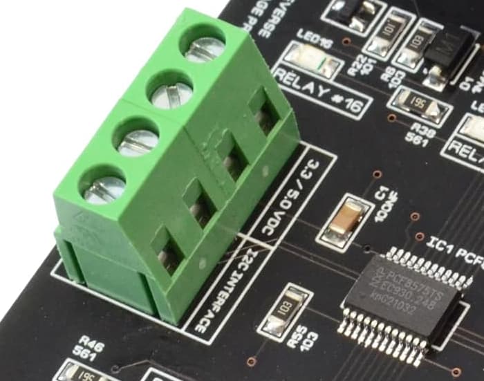
I just have two connections for power and two for data
it was mentioned
Do you have the address pins of the PCF8575 connected to force the address used?

If you connect four, everyone should have its own unique address. (but that is step 2)

Do you have an I2C scanner to see if the address is correct?
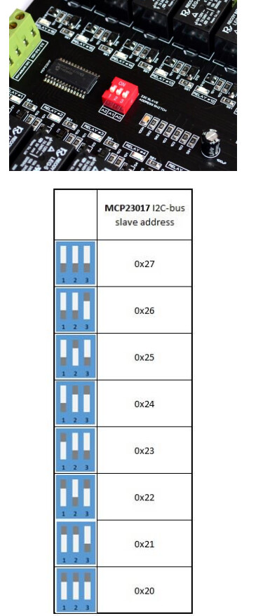
Not sure "connect four" .. to set address. I was just using dip switches per manual / table
I have googled around and lots of older videos on this and that is what I followed but maybe there is a new means to set board ID, scan board, connect then define in code as part of array.
"..Does the I2C scanner sketch find each of the boards on a unique address ? " -> No.
sketch using. Baseline of just first board which is "20"
//
//    FILE: PCF8575_isConnected.ino
//  AUTHOR: Rob Tillaart
// PURPOSE: demo device detection
//     URL: https://github.com/RobTillaart/PCF8575


#include "PCF8575.h"

//  adjust addresses if needed
PCF8575 PCF(0x20);


void setup()
{
  //  while(!Serial);  //  uncomment when needed
  Serial.begin(115200);
  Serial.println(__FILE__);
  Serial.print("PCF8575_LIB_VERSION:\t");
  Serial.println(PCF8575_LIB_VERSION);
  Serial.println();

  Wire.begin();

  if (!PCF.begin())
  {
    Serial.println("could not initialize...");
  }
  if (!PCF.isConnected())
  {
    Serial.println("=> not connected");
  }
  else
  {
    Serial.println("=> connected!!");
  }
}


void loop()
{
}


//  -- END OF FILE --
I set baud on serial monitor to 115200 (also tried update sketch and monitor at lower 9600 without change):
Output on runs
17:33:12.011 -> could not initialize...
17:33:12.011 -> => not connected
09:43:04.167 -> could not initialize...
09:43:04.167 -> => not connected
09:44:25.920 -> could not initialize...
09:44:25.920 -> => not connected
still getting ok when pusing sketch but serial monitor response:
17:33:12.011 -> => not connected
09:43:04.167 -> could not initialize...
09:43:04.167 -> => not connected
09:44:25.920 -> could not initialize...
09:44:25.920 -> => not connected
I saw some youtubes on code that did a cycle scan for I2C connected devices ever 10 seconds but did not see any code examples if someone has link to that to do continual scan vs upload sketch to test connected device.
I don't see a common ground connection between your R4 and either I2C relay board. You should make sure you have this and then re-run your I2C scanner code.
Trying to think of another means to get baseline that serial monitor is working. "not connected" is response... that I assume would be same return serial communication as if board connected and gave ??? some response.
To make it even simpler, run the I2C scanner sketch to see if the board is detected. This is the first step. If this does not detect your board, then your code will not work.
No, that sketch only tests the connection at address 0x20 (unless you change it); it's not a scanner.
You can find the correct sketch in the IDE examples.
So if you have a more generic but debug sketch to scan serial ports, I am glad to learn. This is my first use of Ardunio and IOT.. Not new to concepts of serial /baud etc.. but this is all new so not much of baseline, hense post is a bit open ended.
It's an example for the Wire library included with the AVR boards package. There are no example sketches for the Wire library in the Renesas_UNO boards package used for the UNO R4.
// --------------------------------------
// i2c_scanner
//
// Version 1
//    This program (or code that looks like it)
//    can be found in many places.
//    For example on the Arduino.cc forum.
//    The original author is not know.
// Version 2, Juni 2012, Using Arduino 1.0.1
//     Adapted to be as simple as possible by Arduino.cc user Krodal
// Version 3, Feb 26  2013
//    V3 by louarnold
// Version 4, March 3, 2013, Using Arduino 1.0.3
//    by Arduino.cc user Krodal.
//    Changes by louarnold removed.
//    Scanning addresses changed from 0...127 to 1...119,
//    according to the i2c scanner by Nick Gammon
//    http://www.gammon.com.au/forum/?id=10896
// Version 5, March 28, 2013
//    As version 4, but address scans now to 127.
//    A sensor seems to use address 120.
//
//
// This sketch tests the standard 7-bit addresses
// Devices with higher bit address might not be seen properly.
//

#include <Wire.h>


void setup()
{
  Wire.begin();
  Serial.begin(115200);
  Serial.println("\nI2C Scanner");
}


void loop()
{
  byte error, address;
  int nDevices;
  Serial.println("Scanning...");
  nDevices = 0;
  for (address = 1; address < 127; address++ )
  {
    // The i2c_scanner uses the return value of
    // the Write.endTransmisstion to see if
    // a device did acknowledge to the address.
    Wire.beginTransmission(address);
    error = Wire.endTransmission();
    if (error == 0)
    {
      Serial.print("I2C device found at address 0x");
      if (address < 16)
        Serial.print("0");
      Serial.print(address, HEX);
      Serial.println("  !");
      nDevices++;
    }
    else if (error == 4)
    {
      Serial.print("Unknown error at address 0x");
      if (address < 16)
        Serial.print("0");
      Serial.println(address, HEX);
    }
  }
  if (nDevices == 0)
    Serial.println("No I2C devices found\n");
  else
    Serial.println("done\n");
  delay(5000);           // wait 5 seconds for next scan
}
There is a world of difference between an I2C device being present on an address and actually connecting to that address but at least you know that the device exists
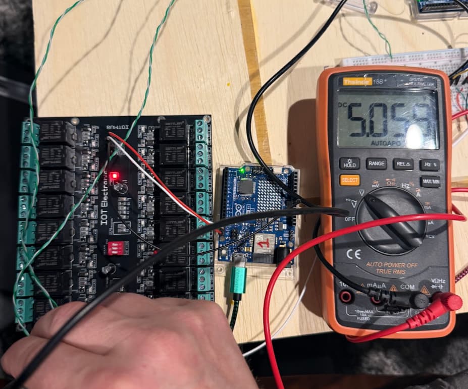
so to root cause.. If I power via USB the arduino. And only from that connect the four cables to the 16 channel relay boards, then it communicates. But if I power the boards with DC power direct.. and the Arduinio the same source also.. it fails. ( it power on all , but the board 16 channel boards "click" once then go silent, almost like not enough power or bad signal)
Concern I have is that 4+ boards hanging off that 5v power connector + other misc devices will be too much load for the ardunio.
Questions
Is there a means to check output / load off that 5v pin?
Is there a means to check on board total load that its within safe range?