@charanpatel_k when you get multiple requests for your code, and it hasn't changed between requests, it's easiest to just point to your first posting of your present code. E.g. "See post # xx". That way, everyone gets the 'state of the art' version, with little confusion.
As for your original post, and subsequent answers, the ambiguity is whether you want four waveforms with unique offsets, or two pairs doing the same thing. Your information does not answer that critical difference.
Hi, @charanpatel_k
Can you please post a diagram of the outputs you need showing how they are with respect to each other?
Thanks.. Tom.. 


Hi Guys,
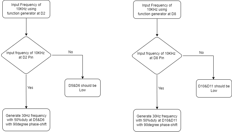
I am stuck at end. I need to enable D2(for D5,D6)&D8(for D10&D11)when ever this D2 & D8 will sense some input frequency this should generate output accordingly.
same 30Hz frequency with 50%duty and 90degree phase shift
D2- should enable D5 and D6
D8 - should enable D10,D11
Hello charanpatel_k
Consider:
//https://forum.arduino.cc/t/phase-shift-between-pins/1170591
//https://europe1.discourse-cdn.com/arduino/original/4X/7/e/0/7e0ee1e51f1df32e30893550c85f0dd33244fb0e.jpeg
#define ProjectName "Phase shift between Pins"
#define NotesOnRelease "1"
// -- some useful text replacements used
#define mod %
// make variables
constexpr uint8_t Pins[] {5,6,10,11};
constexpr uint8_t Pattern[][sizeof(Pins)]
{
  {1,1,0,0},
  {0,1,1,0},
  {0,0,1,1},
  {1,0,0,1},
};
// make support
void heartBeat(int LedPin, uint32_t currentMillis)
{
  static bool setUp = false;
  if (!setUp) pinMode (LedPin, OUTPUT), setUp = !setUp;
  digitalWrite(LedPin, (currentMillis / 500) % 2);
}
// make application
void setup()
{
  Serial.begin(115200);
  Serial.print("Source: "), Serial.println(__FILE__);
  Serial.print(ProjectName), Serial.print(" - "), Serial.println(NotesOnRelease);
  for (auto Pin:Pins) pinMode(Pin,OUTPUT);
  Serial.println(" =-> and off we go\n");
}
void loop()
{
  uint32_t currentMillis = millis();
  heartBeat(LED_BUILTIN, currentMillis);
  static uint32_t microsNow=micros();
  if (micros()-microsNow>=8333)
  {
    microsNow=micros();
    static uint8_t number=0;
    uint8_t element=0;

    for (auto Pin:Pins)
    {
      digitalWrite(Pin,Pattern[number][element]);
      element++;
    }
    number=(number+1) mod (sizeof(Pattern)/sizeof(Pattern[0]));
  }
}
HTH
Here we are not giving any input pins.
Can you see my recent post. Then, It would be helpful.
You can do a digital read of those two pins in the ISR part of the code I sent you and incorporate it into the 'if' statement that governs the writing of the output pins.
However, as usual, you seem to be lacking in detail as to what the default condition of the output pins should be. Are you happy just to leave them at the state they happen to be when they are disabled?
// Working code of 5,6,10&11 pin with 30Hz & 50%duty
int starttime = 0;
int status = 0;
// void StartTimer();
void StopTimer();
void first();
void second();
ISR(TIMER1_COMPA_vect){
  static int times = 0;
  times = (times + 1) & 3 ;
  if(times == 0) { digitalWrite(5, HIGH); digitalWrite(10, HIGH);}
  if(times == 1) { digitalWrite(6, HIGH); digitalWrite(11, HIGH); }
  if(times == 2) { digitalWrite(5, LOW);  digitalWrite(10, LOW); }
  if(times == 3) { digitalWrite(6, LOW);  digitalWrite(11, LOW);}
}
void setup() {
  Serial.begin(9600);
  pinMode(2, INPUT);
  pinMode(5,OUTPUT);
  pinMode(6,OUTPUT);
  pinMode(8, INPUT);
  pinMode(10,OUTPUT);
  pinMode(11,OUTPUT);
  cli();//stop interrupts
}
void starttimer1(){
  int PWM = pulseIn(8, HIGH);
  int frequency = 500000 / PWM ;
  Serial.println(frequency);
  // if(11000 < frequency < 13000)
  if((frequency>9000)&&(frequency<13000))
  {


      TCCR1A = 0;// set entire TCCR1A register to 0
  TCCR1B = 0;// same for TCCR1B
  TCNT1  = 0;//initialize counter value to 0
  // set compare match register for 120 Hz increments
  OCR1A = 130;
  // turn on CTC mode
  TCCR1B |= (1 << WGM12);
 // Set CS12 and CS10 bits for 1024 prescaler
  TCCR1B |= (1 << CS12) | (1 << CS10);
  // enable timer compare interrupt
  TIMSK1 |= (1 << OCIE1A);
    digitalWrite(5,LOW);
    digitalWrite(6,LOW);

  sei();//allow interrupts
    Serial.println("frequency");

    if(starttime==1){
      starttime++;
    }

  }
  else{
    digitalWrite(10,LOW);
    digitalWrite(11,LOW);

  StopTimer();
   starttime=1;
  }

}

void starttimer2(){
  int PWM = pulseIn(2, HIGH);
  int frequency = 500000 / PWM ;
  Serial.println(frequency);

  // if(11000 < frequency < 13000)
  if((frequency>9000)&&(frequency<13000))
  {
          TCCR1A = 0;// set entire TCCR1A register to 0
  TCCR1B = 0;// same for TCCR1B
  TCNT1  = 0;//initialize counter value to 0
  // set compare match register for 120 Hz increments
  OCR1A = 130;
  // turn on CTC mode
  TCCR1B |= (1 << WGM12);
 // Set CS12 and CS10 bits for 1024 prescaler
  TCCR1B |= (1 << CS12) | (1 << CS10);
  // enable timer compare interrupt
  TIMSK1 |= (1 << OCIE1A);
    digitalWrite(10,LOW);
    digitalWrite(11,LOW);
  sei();//allow interrupts

  // analogWrite(5,128);
  // analogWrite(6,128);

  if(starttime==1){
  starttime++;
  }
  else{
    digitalWrite(5,LOW);
    digitalWrite(6,LOW);
  StopTimer();
   starttime=1;
  }
}
}

void StopTimer()
{
  TCCR0A = 0;
  TCCR0B = 0;
  TCCR1A = 0;
  TCCR1B = 0;
  TCCR2A = 0;
  TCCR2B = 0;
}

void loop() {
  // put your main code here, to run repeatedly:
  starttimer1();
  starttimer2();
}
This code giving me 25Hz with 50%duty and phase is working. But I want 30Hz frequency at D5,D6,D10&D11.
When D2 is High- D5 &D6 only should work
when D8 is High - D10&D11 only should work
can you check this.........!
Can anyone check. I think I have explained my problem-statement in a proper way and what I am facing issue in Code also.
You have changed my code in a way that totally breaks the function.
Why did you do this?
Especially when I said
So why did you hack at my code and break it. This code only uses Timer 1. None of the other timers are involved, yet you drag them into your mutilated version of my code and wonder why it no longer functions like it used to do.
The StopTimer function is affecting all timers not just Timer 1 why?
You only need to add a digital read to the ISR for each of your enable pins.
Did my original code produce the correct frequency for you?
Well you haven't, because you have still not stated what levels the stopped wave forms should have.
As they were when stopped, or HIGH or LOW.
You should also use the pin mode function on the two enable pins to make them INPUT_PULLUP in the setup fuction.
@charanpatel_k You would do really well if you were to produce a simple drawing showing the signals and their relationships. Your word salad descriptions (translation is failing you, if that's what it is), leave so much out that it is very hard to determine what it is you really want.
A picture is worth a thousand words. Draw out a complete timing cycle for one or both sets of pins, and completely define the signal relationships. It can be pencil-on-napkin, take a picture of it.
Or at least point out which one of the waveforms shown in post #18 or post #19 is the one you want.
AND also what you want the disabled signal logic levels to be.
Finally please tell us what the level of your programming skills are. You appear with code driving timers producing PWM which would make us think they were pretty good. But then you spoil it by not being able to take any of the advice you are given.
Hi,
I want post #19& sorry for doing your code in that way. I have just tried of doing that. sorry from myside.
I will tell you want I am trying to do
Want PWM's as post #19
1)Total 6 pins : Input pins:D2,D8
Output pins:D5,D6,D10,D11
2) When Input of Some 10KHz individually at D2-D5,D6 should generate frequency of 30Hz with 50% duty with phase 90degree between two Pins.
3) When Input of Some 10KHz individually at D8-D10,D11 should generate frequency of 30Hz with 50% duty with phase 90degree between two Pins.
Once again sorry guys.
Good, one clear piece of information.
Sadly points 2) and 3) are totally incomprehensible.
What is this " When Input of Some 10KHz "? from where is it coming from ?
What pin is is coming in on?
What is the tolerance of this mystery, signal in terms of + / - Hz that will cause this triggering to occur?
Is it coming on on two pins or just one?
If just one pin then what is the difference between 2) and 3)?
What else does your code have to do at the same time?
Drip feeding new information like its is very annoying and makes the work we have done for you useless. I did work for over two hours on that first pice of code I posted.
Is there anything else you need to tell us about this project that might affect the code?
It would help if you told us what you are actually trying to do with the whole of this project. I suspect your silence over the weekend, is a sign that this is some sort of academic project you have been given to do. If so what was your project description you were given?
-I need to generate +30Hz frequency and 50%duty cycle at D5,D6,D10,D11 as I told you earlier.
-Phase shift should be done as Post#19.
-when it comes to input pins which you are asking
we are going to use function generator and feed the 10KHz signal at D2.Whenever we are feeding signal at D2 only D5 and D6 should work. D10,D11 should be Low.
& same applies in case of D8,D10&D11.
-Whenever we feed 10KHz signal at D8,only D10&D11 should work.D5,D6 should be low.
Any more questions for answering Pls let me know.
I hope you got an idea atleast now.
And also I just want to know that, Is it possible what I am trying to achieve?
So our problem is, the answer involves knowing unequivocally what it is you want to do; and that, we have been trying to discern - for quite a while now.
Yes lot of questions have not been answered from my last post.
Plus the outstanding question of what should be the state of the signal lines when this 10KHz stops?
Plus the outstanding question of what should be the state of the signal lines when this 10KHz stops?
When 10KHz stops all 4 outputs should be Low.
What pin is is coming in on?
-At D2 & D8
Is it coming on on two pins or just one?
-Two pins will be used
D2 is for D5&D6
D8 is for D10&D11
If just one pin then what is the difference between 2) and 3)?
-No two pins are functional
What else does your code have to do at the same time?
-As I told you when it comes to input pins which you are asking
we are going to use function generator and feed the 10KHz signal at D2.Whenever we are feeding signal at D2 only D5 and D6 should work. D10,D11 should be Low.
& same applies in case of D8,D10&D11.
-Whenever we feed 10KHz signal at D8,only D10&D11 should work.D5,D6 should be low.
Phase shift is like post#19
Hallelujah Hallelujah
Hallelujah
Hallelujah
Halle ---- lujah
At last.
Aha well back to earth.
So you are saying that is the whole of the code and that is a finish to it and it won't do anything else ever?
Also unanswered:-
Your answer
Not really an answer is it? Every measurement has a tolerance that must be the first thing you should learn.
So why are you injecting 10KHz in the first place? Why are you using a signal generator that will have to supply four different conditions to the input. As a real life project this makes no sense at all.
The other thing is that you seem to have painted yourself into a corner. Once you have interrupts going producing your quadrature signals in a very efficient way, doing any accurate measurement of a frequency is going to be impossible. This is because while the processor is running that ISR it can't accept any other interrupt until it is finished. This will cause jitter on anything measured.
If this was a real project, and for some bazaar reason this is exactly what you wanted to do, I would do the detection of the incoming 10KHz with a MC14046B Phase lock loop to do the detection of the 10KHz, with some sort of switching arrangement to direct the "locked" output signal to what ever pin you want it to go to.
Or use two chips each one monitoring a separate 10KHz signal.