sorry, but my last topic was unsuccesful, so ill start a new one!
well, i still have the photo interuptor, and i still cant get it working, i have 3 of them, 2 with 3 pins, and one of them has four pins, and i couldent get the 3 pin ones working, and the four pin one, i have no idea how to hook it up...
well, i pulled these out of a printer, and the only number i can get out of them is:
41 5
.0D:
( exactly like that ) and that is for the 3 pin one...
edit:
o yea, and me knowing hebrew, it looks like there are 2 letters from the hebrew alphabet. incase it helps, and the 4 pin one has white letters that say "004w" and ontop it looks like "ROHM, or KOHM" and under the letters the numbers are "574"
And how might i hook up a 4 pin photo interupter to an analog pin?
edit edit:
i found a data sheet for it, but i have to subscribe to these asshole's site.... so tell me if you find one while i try to sign up...
thnks
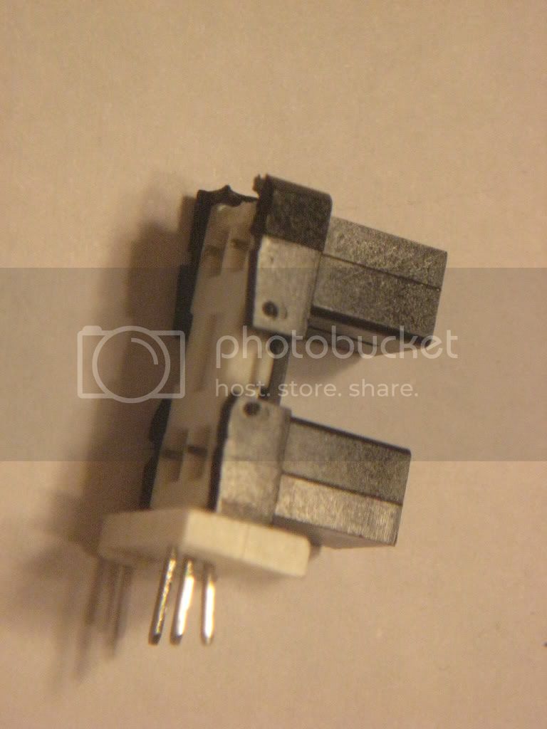
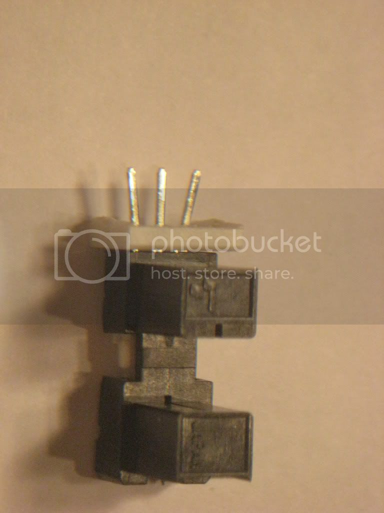
lol not that it helps now..... but i got my hands on a good camera and took some hi res photos of both the types i had, so maybe u can figure out the 3 pin one buy the pictures...
i'm guessing the 3 pin one uses the same ground for both connections, and thats how they get it down to 3 pins?
It could be both grounds on one pin, but it also could also be the anode and collector (+volts) on one pin. Or it could be a twin sensor photodetector without the LED. The picture may help, but I would focus on the 4 pin one for now because you have the connection info.
roger that, im uploading the pictures of both this, and the circuit boards of all the controllers, and stuff, ill post back in like 5 mins with the pics
wooooooooooooow, i'm trying this and it's not working, can u tell me what i'm doin wrong?
i got everythin hooked up good, except it wont work!
i'm using the example switch test in the arduino software, and incase u dont got it lying round, here it is:
/*
 * Button
 * by DojoDave <http://www.0j0.org>
 *
 * Turns on and off a light emitting diode(LED) connected to digital
 * pin 13, when pressing a pushbutton attached to pin 7.
 *
 * http://www.arduino.cc/en/Tutorial/Button
 */

int ledPin = 13;                // choose the pin for the LED
int inputPin = 7;               // choose the input pin (for a pushbutton)
int val = 0;                    // variable for reading the pin status

void setup() {
  pinMode(ledPin, OUTPUT);      // declare LED as output
  pinMode(inputPin, INPUT);     // declare pushbutton as input
}

void loop(){
  val = digitalRead(inputPin);  // read input value
  if (val == HIGH) {            // check if the input is HIGH
    digitalWrite(ledPin, LOW);  // turn LED OFF
  } else {
    digitalWrite(ledPin, HIGH); // turn LED ON
  }
}
got everything hooked up how u said, and i'm confused.
sorry about the abbreviations, ill try to spell stuff out more, and as far as i know the arduino is fine, it turns into a capacitive sensor when i unhook some wires, but led blink works, and i have that exact value resistor, and everything!
I would try hooking it up to an Analog input and reading the return. Maybe the sensor is not a HIGH/LOW but a variant you could then use something like
If (Pin > 250){serial.print("On");
If (Pin < 250){serial.print("Off");
yes, i see what you mean, but how could i hook it up to analog, it has 4 pins?
do i need to instead of hooking to the digital input, to an analog input?
Ok. You can verify you have the diode working by pointing a digital camera at it.
You should see a glow in the display. MEM's wiring is the one to go by.
If you look at the device you'll see the diode symbol on it. That end is the diode. The triangle end is the anode and goes to the resistor the resistor to +5v the other end the flat end goes to ground.
The other end is the photo transistor. You need to connect a 10k resistor to +5v then run the other end of the resistor to a digital pin, run that digital pin to pin 3 on the photointerrupt and then run pin 4 on it to ground. When mem said 'treat it as a switch' you follow this but you replace the button with the two phototransitor connections wired properly.
The 10k resistor going to +5 causes the digital pin to be high with +5v. The phototransistor will pull it low. Just look for a low on that digital pin and you know the beam has been tripped. You don't want to short +5v to ground without the resistor the resistor is needed to keep current low.
sorry about the abbreviations, ill try to spell stuff out more, and as far as i know the arduino is fine, it turns into a capacitive sensor when i unhook some wires, but led blink works, and i have that exact value resistor, and everything!
Ok. You can verify you have the diode working by pointing a digital camera at it.
You should see a glow in the display. MEM's wiring is the one to go by.
If you look at the device you'll see the diode symbol on it. That end is the diode. The triangle end is the anode and goes to the resistor the resistor to +5v the other end the flat end goes to ground.
no resistor? its a small led, i dont know if itll burn it out, or if it will be ok

