While I'm not exactly new to using an Arduino, I'd still put my level of experience slightly above novice. I apologize in advance for my ignorance in what may seem obvious to you. Any and all suggestions are greatly appreciated.
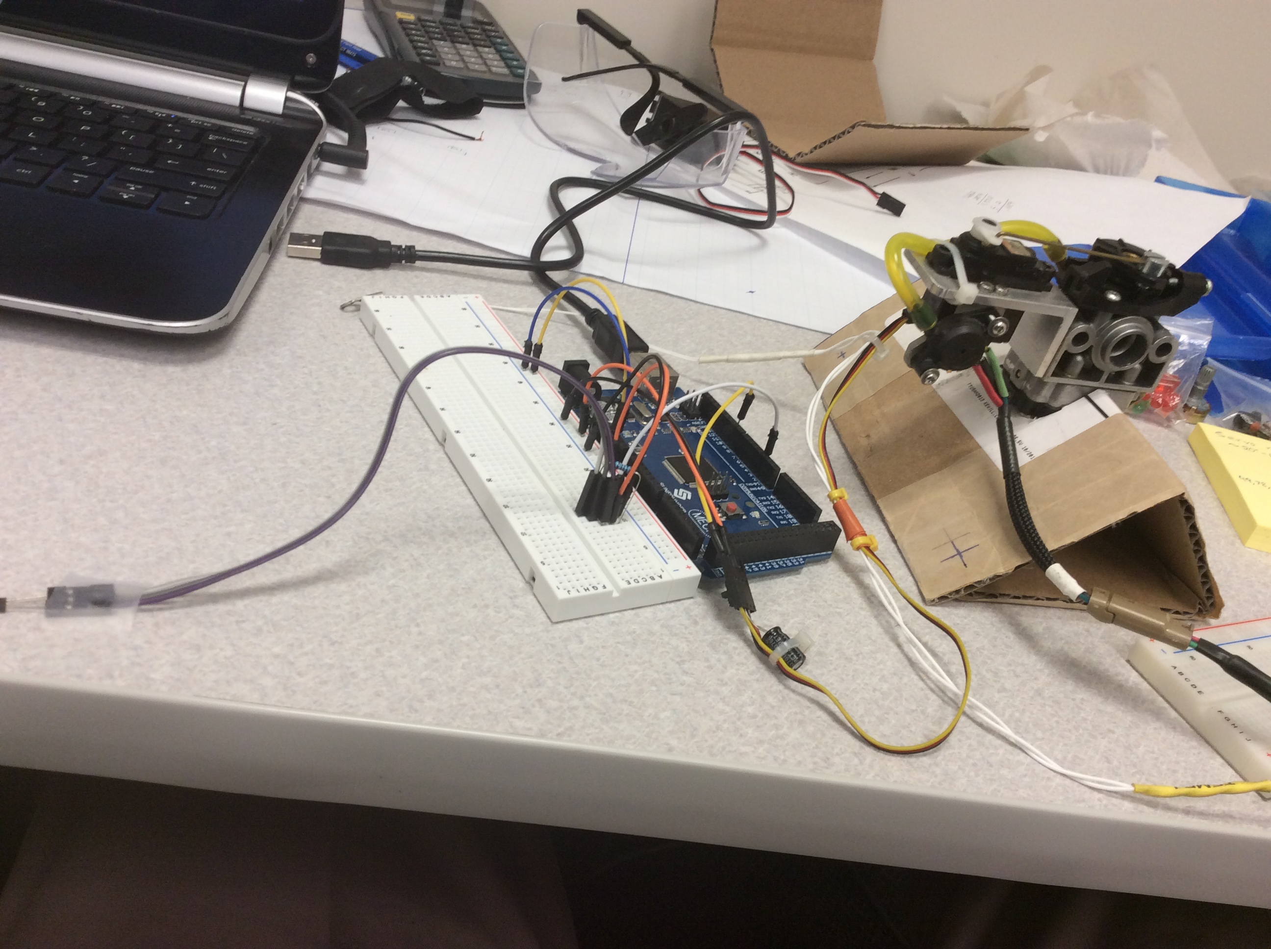
As the subject title states, I am trying to control the opening and closing of a throttle via a hobby servo but also implementing PID control. I'm using the <PID_v1.h> library. Currently, I'm using a hall sensor to calculate the RPM of a fan that I can control with a potentiometer (Image attached). In a different setup I observed that with the magnets attached to the fan, max RPM was approximately 2500 RPM which is my reason for choosing that number in the code when mapping the input. I have the RPM of the fan as Input, a Setpoint currently specified at 1500. I believe the Output should be the angle of the servo which will ultimately dictate RPM by throttle control. When I run the code below the servo is not responding and I'm getting an output value of 0.
You'll notice in the code that I commented out the variable "Output" in the loop function as I felt it was circumventing the PID control (not sure if I'm correcting for thinking this) as it would work flawlessly regardless of the gain values. I'm still learning as I go but I'm concerned I'm no longer going in the right direction. Once again, any help is appreciated. Thank you.
#include <PID_v1.h>
#include <Servo.h>

Servo myServo;

volatile byte half_rev;

unsigned int rpm;
unsigned long previousTime;

double Setpoint;    // will be the desired throttle opening for a desired rpm value
double Input;       // rpm reading from hall sensor
double Output;      // throttle
//int Out = (int) Output;

//PID parameters
double Kp = 10, Ki = 0, Kd = 0;

//create PID instance
PID myPID(&Input,&Output, &Setpoint, Kp, Ki, Kd, REVERSE);

void setup()
{
  Serial.begin(9600);
  //Hardcode the rpm value
  Setpoint = 1500;

  //Turn the PID on
  myPID.SetMode(AUTOMATIC);

  //Adjust PID values
  //myPID.SetTunings(Kp, Ki, Kd);

  //Set the output limits
  myPID.SetOutputLimits(0,180);

  //Set servo motor to pin 9
  myServo.attach(9);

  attachInterrupt(0, rpm_calc, RISING);
  half_rev = 0;
  previousTime = 0;
}

void loop()
{
  if (half_rev >= 20) // RPM is updated every 20 counts of a rising edge. For a better RPM resolution increase but for faster update decrease.
  {
    rpm = 30*1000/(millis() - previousTime)*half_rev; // NOTE: this works for two interrupts per full rotation.
    previousTime = millis();
    half_rev = 0;
  }
  //Read the value of the calculated rpm from the hall sensor. Motor input: 0 to ~2500.
  Input = map(rpm, 0, 2500, 0, 255);
  //Output = map(Input, 0, 255, 180, 0);

  myPID.Compute();    //PID calculation

  //Write the output as calculated by the PID function
  myServo.write(Output); // Servo motor is set to digital pin 9 this is a pwm pin
  //analogWrite(9,Output); // Servo motor is set to digital pin 9 this is a pwm pin
  //digitalWrite(servoPin,Output);

  //Send data by serial for plotting
  /*Serial.print(Input);
  Serial.print(" ");
  Serial.println(Output);
  Serial.print(" ");
  Serial.println(Setpoint);*/

  Serial.print("RPM =\t");
  Serial.print(rpm);
  Serial.print("\tPWM =\t");
  Serial.print(Input);
  Serial.print("\tOutput =\t");
  Serial.println(Output);
}

void rpm_calc()//This function is called whenever a magnet/interrupt is detected by the arduino
{
  half_rev++;
}
I'm slightly confused by your question but here's my attempt at an answer. My RPM and input are one in the same. It varies between 0 and ~2500 because it fan speed that I control with the potentiometer, if that makes sense. I apologize if I didn't initially make that clear.
First, the error term is defined as setpoint - input. Your setpoint rpm is 1500, but your input rpm has been mapped down to 0-255. I think that that setpoint and input need to use the same scale/values for the error term to be correct. In your case 1500 -0 and 1500 - 255 both leave a large error term regardless of the input rpm. What led you to map the input rpm as you have done?
Second, you have defined the process as REVERSE acting with
PID myPID(&Input,&Output, &Setpoint, Kp, Ki, Kd, REVERSE);
The PID will either be connected to a DIRECT acting process (+Output leads
to +Input) or a REVERSE acting process(+Output leads to -Input.) we need to
know which one, because otherwise we may increase the output when we should
be decreasing. This is called from the constructor.
What is the relationship of the servo position and the rpm? Should this not be a DIRECT process? I say this, because the first issue where the error should lead to increasing input to reduce the error (i.e. the setpoint is not met) and should lead to full on output, but you are getting 0 for output and not seeing the servo move.
First, the error term is defined as setpoint - input. Your setpoint rpm is 1500, but your input rpm has been mapped down to 0-255. I think that that setpoint and input need to use the same scale/values for the error term to be correct. In your case 1500 -0 and 1500 - 255 both leave a large error term regardless of the input rpm. What led you to map the input rpm as you have done?
I didn't even consider that. Thank you for pointing that out. Come to think of it my initial reason for doing so might be flawed. I'm more familiar with using the map() function to map analog values to 8 bits. In the next line of code, that I commented out, Input would then be mapped accordingly to actuate the servo but as previously mentioned I felt PID wasn't in control at this point.
What is the relationship of the servo position and the rpm? Should this not be a DIRECT process? I say this, because the first issue where the error should lead to increasing input to reduce the error (i.e. the setpoint is not met) and should lead to full on output, but you are getting 0 for output and not seeing the servo move.
I'm still wrapping my head around the inner workings of this library but I thought REVERSE would do exactly what you described (i.e., if rpm is below setpoint then the servo would actuate to open the throttle and vice versa).
I'm still wrapping my head around the inner workings of this library but I thought REVERSE would do exactly what you described (i.e., if rpm is below setpoint then the servo would actuate to open the throttle and vice versa).
This is a mechanical issue. If the servo at 0 degrees is closed throttle (slow rpm) and the servo at 180 degrees is open throttle (high rpm) then the process is DIRECT acting.
Instead of a "throttle" think you have the servo turning a potentiometer, but the principle is the same. If more pot turn degrees leads to more fan speed, that's DIRECT. If more pot turn leads to slower fan speed, then the process is REVERSE.
The Input and Setpoint have to be in the same units.
The Output is arbitrary, with the default limits being 0.0 and 255.0. If you are using Output to drive a servo you probably want to set the limits to 0.0 and 180.0 (angle) or 1000.0 and 2000.0 (microseconds) depending on whether you are calling servo.write() or servo.writeMicroseconds().
If higher Output means higher Input you have a DIRECT system (like higher PWM to a motor increases RPM). If higher Output means lower Input you have a REVERSE system (like higher PWM to a refrigerator decreases temperature).
Thank you to you both for clearing that up. It makes more sense to me now. Implementing that has proven to push me in the right direction. Now the servo is responding but only sometimes. I'm not sure if this is because of my shaky hands trying to firmly hold the fan above the hall sensor or something code related. Basically when I'm changing the RPM when it's close to the setpoint (+/- 200) it's very active. The further away I am the less responsive the servo but the output displayed on the serial monitor is correct. Could it be a communication problem or lag? Either way, thanks for the help thus far. I'll continue to experiment to see what's what?