Hello All,
While I'm not exactly new to using an Arduino, I'd still put my level of experience slightly above novice. I apologize in advance for my ignorance in what may seem obvious to you. Any and all suggestions are greatly appreciated.
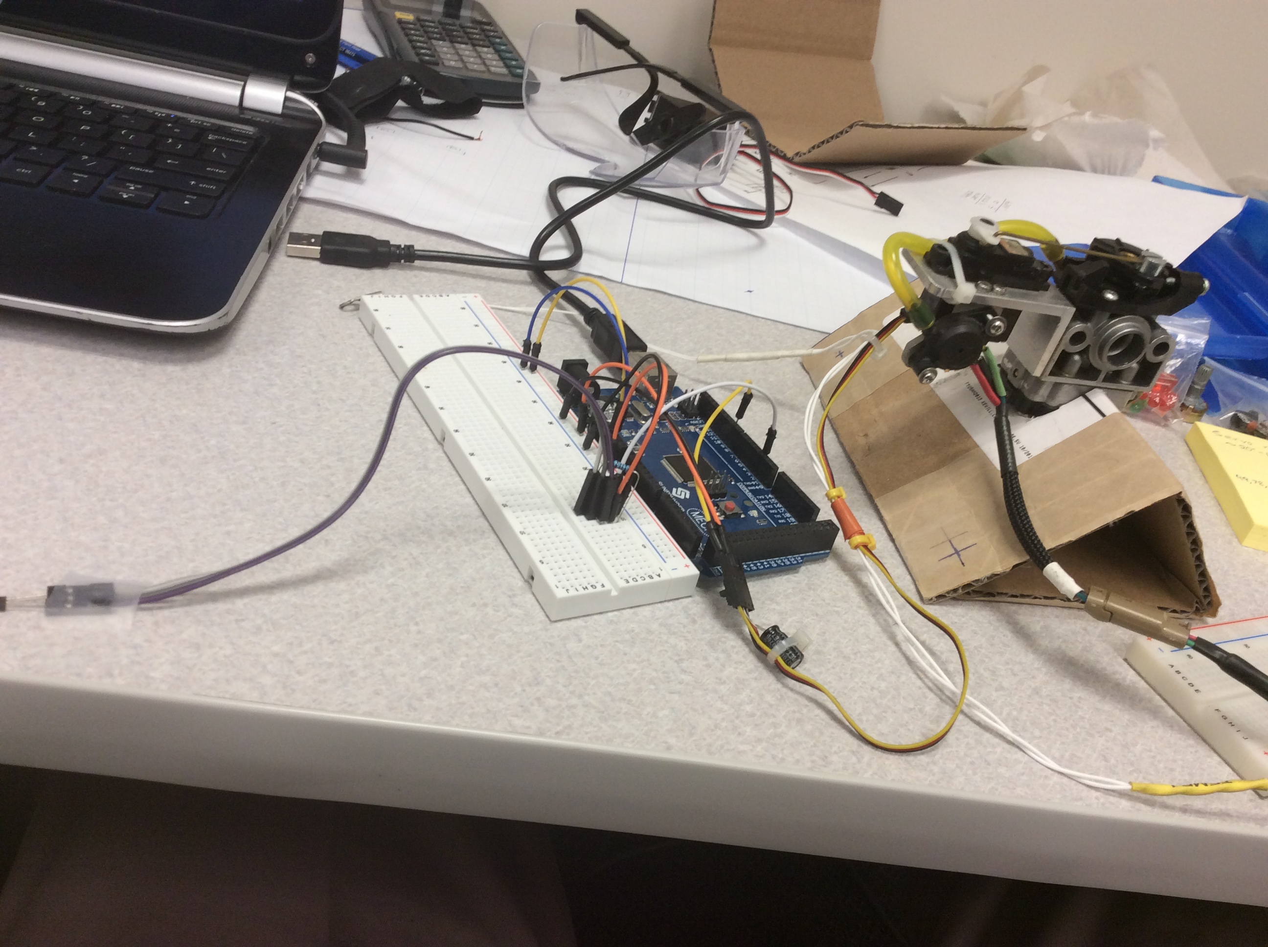
As the subject title states, I am trying to control the opening and closing of a throttle via a hobby servo but also implementing PID control. I'm using the <PID_v1.h> library. Currently, I'm using a hall sensor to calculate the RPM of a fan that I can control with a potentiometer (Image attached). In a different setup I observed that with the magnets attached to the fan, max RPM was approximately 2500 RPM which is my reason for choosing that number in the code when mapping the input. I have the RPM of the fan as Input, a Setpoint currently specified at 1500. I believe the Output should be the angle of the servo which will ultimately dictate RPM by throttle control. When I run the code below the servo is not responding and I'm getting an output value of 0.
You'll notice in the code that I commented out the variable "Output" in the loop function as I felt it was circumventing the PID control (not sure if I'm correcting for thinking this) as it would work flawlessly regardless of the gain values. I'm still learning as I go but I'm concerned I'm no longer going in the right direction. Once again, any help is appreciated. Thank you.
#include <PID_v1.h>
#include <Servo.h>

Servo myServo;

volatile byte half_rev;

unsigned int rpm;
unsigned long previousTime;

double Setpoint;    // will be the desired throttle opening for a desired rpm value
double Input;       // rpm reading from hall sensor
double Output;      // throttle
//int Out = (int) Output;

//PID parameters
double Kp = 10, Ki = 0, Kd = 0;

//create PID instance
PID myPID(&Input,&Output, &Setpoint, Kp, Ki, Kd, REVERSE);

void setup()
{
  Serial.begin(9600);
  //Hardcode the rpm value
  Setpoint = 1500;

  //Turn the PID on
  myPID.SetMode(AUTOMATIC);

  //Adjust PID values
  //myPID.SetTunings(Kp, Ki, Kd);

  //Set the output limits
  myPID.SetOutputLimits(0,180);

  //Set servo motor to pin 9
  myServo.attach(9);

  attachInterrupt(0, rpm_calc, RISING);
  half_rev = 0;
  previousTime = 0;
}

void loop()
{
  if (half_rev >= 20) // RPM is updated every 20 counts of a rising edge. For a better RPM resolution increase but for faster update decrease.
  {
    rpm = 30*1000/(millis() - previousTime)*half_rev; // NOTE: this works for two interrupts per full rotation.
    previousTime = millis();
    half_rev = 0;
  }
  //Read the value of the calculated rpm from the hall sensor. Motor input: 0 to ~2500.
  Input = map(rpm, 0, 2500, 0, 255);
  //Output = map(Input, 0, 255, 180, 0);

  myPID.Compute();    //PID calculation

  //Write the output as calculated by the PID function
  myServo.write(Output); // Servo motor is set to digital pin 9 this is a pwm pin
  //analogWrite(9,Output); // Servo motor is set to digital pin 9 this is a pwm pin
  //digitalWrite(servoPin,Output);

  //Send data by serial for plotting
  /*Serial.print(Input);
  Serial.print(" ");
  Serial.println(Output);
  Serial.print(" ");
  Serial.println(Setpoint);*/

  Serial.print("RPM =\t");
  Serial.print(rpm);
  Serial.print("\tPWM =\t");
  Serial.print(Input);
  Serial.print("\tOutput =\t");
  Serial.println(Output);
}

void rpm_calc()//This function is called whenever a magnet/interrupt is detected by the arduino
{
  half_rev++;
}