Hello I have been looking for information and cant seem to find it anywhere so please help. My circuit has 5vDC. 12vDC is available.
I am trying to drive a piezo transducer buzzer with my Arduino as part of a project. At the moment Im using a radio shack internally driven 273-060 and a boost converter circuit (at 12vDC and a peak of 20vDC) to adjust the volume. I would like to use something like a 273-073 and drive it externally but i cannot find all the information needed.
What i cant find is the duty cycle they recommend, i would assume 50%?
Next is the sound output, i cannot find any datasheets on either product but found these to on similar buzzers, which i will use instead because radio shack is more costly. (but i am testing with the radio shack products i have on hand)
So if i understand this correctly the 273-060 equivalent internally driven has a max voltage of 28vDC and puts out a min 86db at 12vDC.
And the 273-073 equivalent external driven has a max voltage of 15vDC(30v p-p) and when driven at 4.8khz it puts out min 85db at 5vDC(10v p-p)?
So the externally driven (at 5vDC) puts out about the same as the internally drive (at 12vDC). So I could use the externally driven and get rid of my boost converter and still put out the same sound level?
What would be the best way to adjust the volume with the externally driven buzzer?
Thanks
I did some breadboard testing with the radio shack buzzers. Here are the results and new questions.
The external drive seems louder at 5vdc then the internal at 12vdc. Which is good because they are cheaper and i can eliminate the boost converter circuit. Saving time, money, pcb space, and current draw from my 7805. It also sounds clearer than the internal drive.
I would like to know how to set timer1 so the pwm output on pin 9 is 2.5khz and also how-to set it at 4.8khz. The only way i know how to change it is in the following link. Arduino Playground - TimerPWMCheatsheet That is a great example, that i have used before, but doesn't get the frequencies i need.
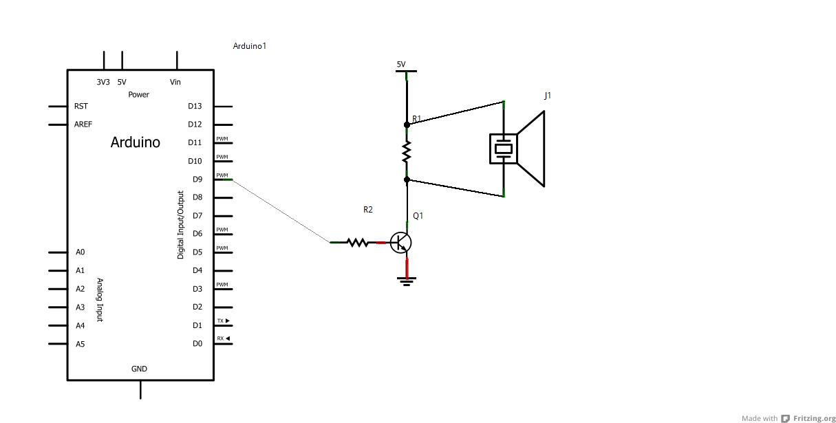
Here is the circuit i am using for others that have trouble finding it.
R1 im using 470ohms. Formula i used (Vcc * 100 ohms) 470ohms is good enough for my testing
R2 1k
Q1 2N4401
I am thinking about using a 12vdc supply for the piezo but i would have to add a 7812 + caps just for the piezo. As my input is 15vDC.
I have searched for hours with no luck. I cannot find a point blank way to change the pwm output, maybe a new function needs to be added to adjust timers?? Some code I could find is below, but think it would work in my application. Could someone explain this and how to use it. I would still like to find out how to change the timers so i can continue to use the analogWrite function for pwm. I wouldn't think it would be very hard, I just cant find the instructions most likely.
void setup()
{
pinMode(11, OUTPUT); // Hardcoded to use pin 11
TCCR2B = 0; // Stop timer2
TCNT2 = 0; // Clear timer2 counter
TCCR2A = _BV(WGM21); // CTC mode, TOP = OCR2A
TCCR2A |= _BV(COM2A0); // Toggle OC2A on Compare Match
OCR2A = 249; // Set timer2 TOP value for 4KHz
}
I think i found a simple solution. Can i just use the tone() function?
tone(buzzerPin, 2500); for 2.5khz
tone(buzzerPin, 4800); for 4.8khz
And if I wanted to set a how long the buzzer was on, use
tone(buzzerPin, 2500, 1000); for 1 second at 2.5khz?
One last question, can i set the PWM frequency for Timer2 to 2.5khz using tone(). Like this????
tone(11, 2500);
digitalWrite(11, LOW);
then change the duty cycle and use the pin normally at the set 2.5khz like this????
analogWrite(11, 127); // for 50%
analogWrite(11, 64); // for 25%
If I have read the tone() information correctly this should work just as stated? This would be a great way to change Timers set frequency if it does work. Please let me know what you think.
One last question, can i set the PWM frequency for Timer2 to 2.5khz using tone(). Like this????
No. tone and PWM use different incompatible modes for the timer. tone uses a combination of prescaler and OCR value to generate an interrupt at the desired frequency. PWM always runs at one of two frequencies (~977 Hz for timer 0; about half that for the other timers).
tone and PWM use different incompatible modes for the timer. tone uses a combination of prescaler and OCR value to generate an interrupt at the desired frequency.
Will using tone() keep the buzzer on and let the rest of my code flow fine until i use notone() to turn it off?? That is why I asked about the analogWrite(11, 128); because it would put out the PWM until i called digitalWrite(11, LOW);
Can you verify the first two things are correct assumptions?
Perfect! Thanks alot, I can order my piezos and continue with this project!
I did some testing with the following code and the results are kind of interesting.
void loop()
{
  digitalWrite(13, HIGH);
  delayMicroseconds(200);
  digitalWrite(13, LOW);
  delayMicroseconds(200);
  hz++;
if (millis() - time >= 20000){
  Serial.print(hz/20);       // prints PWM signal in hz -- 2417hz in this case
  Serial.println("");
  hz = 0;
  time = millis();
}
}
This counts the hz over 20 seconds averages per second and prints it.
This will give a 2417hz reading every time. (probably not totally accurate, because of the time it takes to run code) I then put tone(11, 2500); in the setup(), and it slowed my loop down to 2333hz. Then tried tone(11, 10000); and the reading was 2080.
So the faster i use tone the slower it runs my loop, if i add noTone(); right after Serial.Print, it speeds right back up to the 2417, after it gives the first reading with tone on.
So when tone is on it slows the code down, and the higher the freq used with tone, the more it slow down, turn it off and it speeds right back up.
In my app this doesn't matter but it might help others. Any comments??
The difference is the processor time consumed by the timer/tone interrupt service routine. It is possible to output directly to a pin (no interrupts) but tone does not take advantage of this. For what it's worth, the tone function in the Tiny Core does.
For what it's worth, the tone function in the Tiny Core does.
I am planning putting this on a AtTiny85. Now that i have eliminated the need for the boost converter and reduced my project to 6 in/out pins. Sounds like i have more learning todo now....
Again thanks for the advice, it has been very helpful to me, and hopefully others. (From the original posts you can tell how confused I was about this)
I just remembered im using an interrupt on pin 3 in my code. Is tone() on pin 11 going to affect this?? Or can i just use tone() on pin 9 or 10 to avoid any possible conflict? Or use interrupt 0 on pin 2??
Also one thing i forgot to ask, if i use tone(11, 2500, 10000); i added a 10 sec duration. Will the code continue to flow or will it delay it until the tone stops? I will test this also so i might have an answer soon on my own.
UPDATE: I tested the second question (with the test code above, but read the hz every sec) and have the answer. The code continues to flow while the tone() is on, at the slow rate, then when the duration runs out, the code speeds back up. So YES my code will continue to run while the tone is playing for the duration set.
For what it's worth, the tone function in the Tiny Core does.
I am planning putting this on a AtTiny85.
I believe timer 0 is used for tone on the ATtiny85 processor. In this case, OC0A (pin 0) and OC0B (pin 1) are "hardware direct" pins. For the other pins an interrupt service routine is used.
There is a noticeable audible difference especially at lower processor speeds. A little experimenting and you will be able to determine which pins are "hardware direct".
tnovak:
I just remembered im using an interrupt on pin 3 in my code. Is tone() on pin 11 going to affect this??
Indirectly. Only one interrupt service routine runs at any given moment in time. If the INT1 handler is running, the timer/tone interrupt handler waits and vice versa. Keep the interrupt service code short and simple and you'll be fine.
Or can i just use tone() on pin 9 or 10 to avoid any possible conflict? Or use interrupt 0 on pin 2??
You don't need to worry about that kind of conflict.
Well, on the ATtiny85 processor you will. The pins are heavily "overloaded". For example, the INT0 pin is also SCK, USCK, SCL, ADC1, T0, and PCINT2. You can make use of external interrupts or you can use SPI (Serial Peripheral Interface) but not both.
I will be running the 85 at 16mhz for ease of transition, from the arduino board.
Just reading the 85's datasheet and am going to use the 328 after all. Using a external clock source will use one of my pins (didnt even think about it, duh me), leaving me with only 5.(I need at least 6) Which is okay, it will allow pins for later additions. Will add some cost though.
So now i just need to find out if the interrupts are affected by the use of tone(). vise-versa
You answered this while i was typing...
The interrupt is only used to silence the buzzer so from what you are saying there should be no conflict in my app.
void loop{
if (mutepressed == 0){
  attachInterrupt(1, mute, RISING);
playsound();  // Code making buzzer sound
}
}

void mute(){mutepressed = 1; noTone(11); return;} // noTone() will turn buzzer off just in case it happens to be on at moment of interrupt
There is alot more code but that should be enough to show what the interrupt does.
Again thanks for the help, i have spent days, yes days, trying to find most this information. I have learned more from the few replies you have posted than hours of googling, and I am IMO a very good googler. (have used promoted websites to the #1 position more than once)(also have good skills with adwords)(so like to think i can use the otherside of it too)
tnovak:
I will be running the 85 at 16mhz for ease of transition, from the arduino board.
In my experience, so long as there is enough horsepower to get all the work done, there isn't much difference between 16 MHz and 8 MHz.
Just reading the 85's datasheet and am going to use the 328 after all.
Bummer. I really like the 85 processor. It's fun to see the clever ways people use it.
Using a external clock source will use one of my pins (didnt even think about it, duh me), leaving me with only 5.(I need at least 6) Which is okay, it will allow pins for later additions. Will add some cost though.
The processor has an internal 8 MHz oscillator. It is not nearly as accurate as a crystal but it uses less power and you don't have to tie up any pins for clocking.
However, to get 6 I/O pins on an ATtiny85 you will have to use a "high voltage" programmer. That's the only practical way to turn RESET into an I/O pin.
Now I want to use the 85 even more, but it probably isnt practical for my app. However I am using a tiny13 in a different app, which i am going to replace with a 85. The 13 is powerful enough but i want to learn more about the 85(for other apps in mind) and when buying 25 at a time there is only a $0.21 difference. One app i use the 13 in only uses 78 bytes of mem if i remember right. My external circuit does most the work. When the ignition is on or off the 13 has no power(using no battery). When the ign turns on the chips power is still off, held off by a transistor, then when the ign is turned off the chip powers and holds itself and a relay on(powering a fan and water pump) until it counts away a preset 15 minutes. Then writes output low and is totally off again. If the ign is turned on again, it resets the count by de-powering the chip, until the ign is off again.
Not sure if any of that makes sense, does to me lol.
Works very well, might add thermostat control and/or jumper pin or pot time control, when adding the 85
Back to the previous convo, my 328 uses a output pin to hard reset the chip after user input and eeprom save.(pulls reset pin to low)(which i also forgot about so im up to 7 pins needed again) But if i could software reset the chip, it would be down to 5 I/O's and maybe a 85 would be possible.
Bear in mind that most bootloaders do not behave well when using the watchdog to reset the processor. For the 85 processor this is not a problem (no bootloader) but for an Arduino board it can be a problem.
I have been reading up on the "watchdog" and its uses. I will be testing the code after i receive my 85's. So for now i have plenty of time to make the code nice and neat.
Thanks Again, I'll post when i see how it all works. And am sure will have plenty more questions once i start working on the 100 other ideas that are bouncing around in my head.