djsfantasi:
Five minute limit between posts. Ridiculous)
Ah well, you're on 98, so only 2 more ![]()
djsfantasi:
Five minute limit between posts. Ridiculous)
Ah well, you're on 98, so only 2 more ![]()
oh hate that noob time out deal... silly really.
djsfantasi:
What pin is A0? It’s not pin 0.
It is pin 0 if you do an analogRead().
But if you use that pin marked as A0 as a digital pin for digitalRead() or digitalWrite(), you need to call it AO thus digitalRead(A0) or digitalWrite(A0) else as you say, it would think it was one of the serial pins.
But just to further complicate simplify matters, you can count on from 13 and call A0 etc as 14 etc as in digitalRead(14) or digitalWrite(15) as digital pins.
The scenario you mention (counting pins) is exactly how I started using the analog pins. I switched to using the symbols recently.
So I tried using symbols for the digital pins. For example D3 for the first PWM pin. But it doesn’t compile.
Thanks for all your help. I hope when I get on the workbench, I’ll have this running soon.
Almost 100, your limitations are over, congrats!
I've never tried to call a pin Dx at all, just x, since I've only ever used an Uno where there's no "D" on the silk-screen.
Problem with counting on from 13 to call A0 as 14, etc, is that it ties you to the Uno/nano style. If you took that code to a Mega, where there is an "actual" 14, you would have to renumber. But if you call them A0 etc, then those are correct on either style of board.
Yep! I work with both Unos and Megas. Typically in applications where the other model isn’t appropriate.
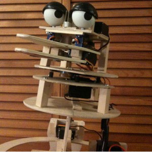
The animatronic @larryd posted is mine. It uses a Mega, MP3 shield and a standalone servo controller with 11 servos. The sketch is actually a run-time module for a proprietary animatronic control language I designed, which is stored on a microSD card.
NOW, I’m over 100 posts.
Thanks again. I’ll return to update you with the results.
djsfantasi:
@wolframore,All the LEDs have been tested and are wired correctly. Cathode to ground; anode to pin.
With series current limit resistors we hope?
Thanks.. Tom.. ![]()
Ok, that was it. I was confused with the pin labeling on the Nano. I apologize for giving you guys a hard time.
I modified my test program to use the set of pins posted by @neiklot, reconnected the LED lead I’d cut and it worked without any further modifications.
I was relieved that I didn’t have to rewire the Nano. It was embedded in the prop. Tomorrow, I’ll change the pin definitions in the production sketch and test again. The only outstanding tasks then are to wire up a battery and connect a switch. I don’t see any problem there.
Thanks again for your patience and help.