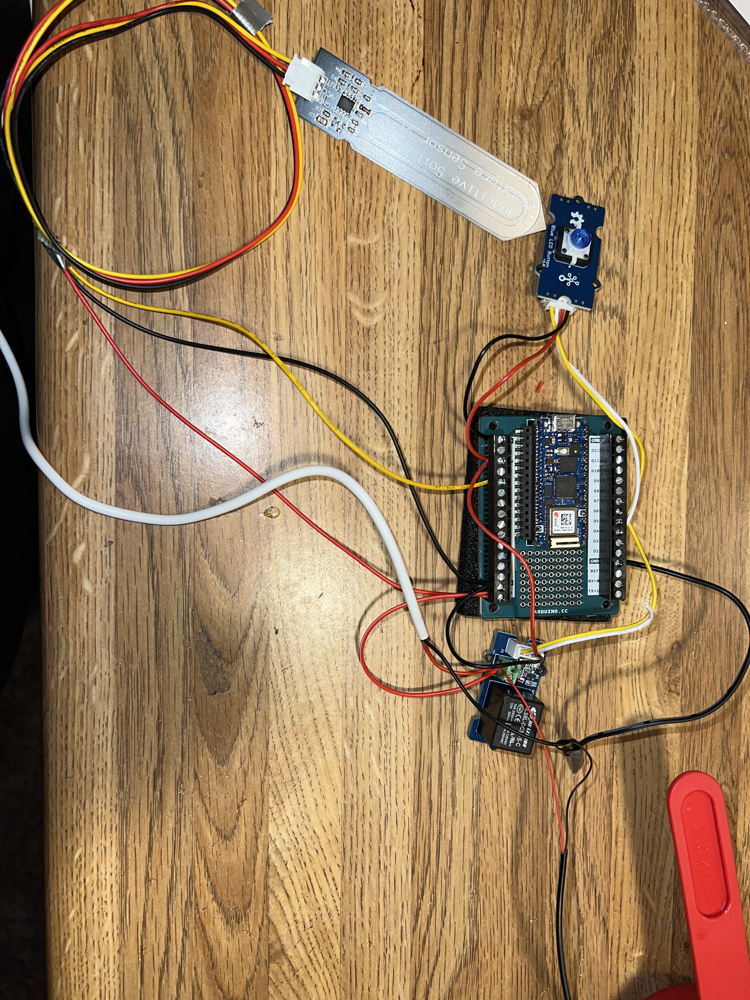
Im new to this but when I short the two inputs on the bottom of the relay the pump works however when trying to use the button or Arduino cloud to activate pump it just clicks. I know it said to keep the grounds close for the pump and power source so I put them both in the same ground. any help is appreciated! If you need a better picture let me know!
can't really determine too much from the pic..
but i can see, maybe you need to take another close look at your tut..
look close at where they got the power supply in relation to the pump and board..
looks like you went the wrong way..
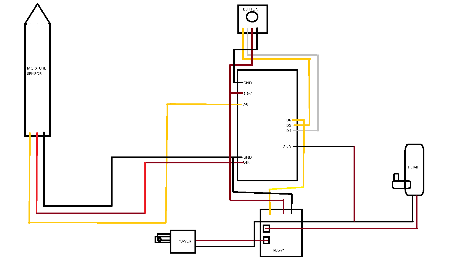
Here is a better picture, I looked over everything and it seems to be good also adjusted terminals to make sure the wires were secure. If it helps the D3 or O3 light flashes on the relay when its trying to turn on. Is there another layout that may work better?
redo pump ground and red wire on relay, should not see any copper..
really probably should take black from power supply and write nut to pump ground then back to board, would look more like tut diagram..
nice..
disconnect pump, check if relay operates properly..
if it does, pump is playing with the power, power pump from separate supply..
if relay does not operate properly, maybe in the code or faulty relay..
Alright so the relay switches on when pump is disconnected, using a secondary power supply I've got it plugged in to the terminal on the relay and grounded and the motor on the other terminal as well as its ground but it doesn't switch anymore even with the secondary power supply.
White PS Cable -Black to Pump Ground, Red to relay -out from relay to pump positive, no other connections for this PS. Just pump and red wire switched thru relay..
Yes that is how it is laid out and then another power supply to VIN and separate ground. Just seems like when current is running through relay terminals it doesn't want to switch.
When testing the relay out to the motor and the ground on the breakout board the pump started to work properly when pressing the button, still trying to figure out how to use it to get the 3.3 though
Okay so when testing the 3.3 v with my DMM at DCV 20 got about 3.24 and then when testing the pump power and ground, still don't know why it works when testing those, it goes very high about 43.0 with my DMM set to DCV 200
Hi,
Remove the gnd connection between the pump power supply and the controller gnd.
Its not necessary and defeats one of the advantages of using a relay.
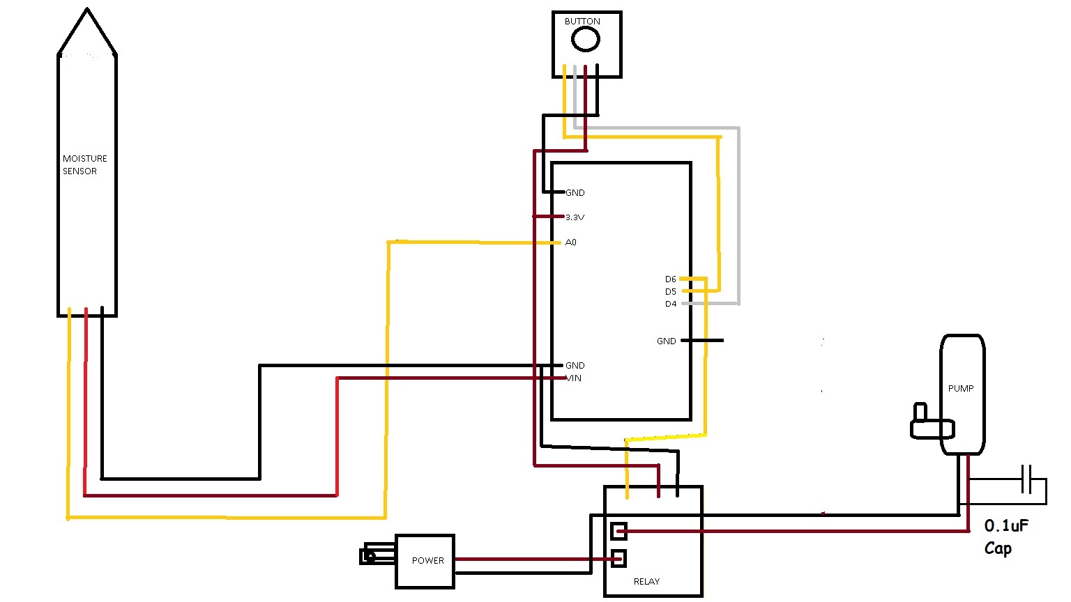
Hello Tom I had done what you said, also in that diagram I forgot to add the boards power supply but that was just another + in to vin and - to ground. taking it out of ground, then moving - directly to secondary power supply's - everything worked. Curious what is the 0.1uF Capacitor for?
Miekush- No not so much clicking for me, it was only clicking when I attempted to switch the relay via button or IoT console
Im unable to reply anymore for the day unfortunatly, I hope you see this miekush and Tom
The result of uploading that made the pump turn on and off correctly, did you want that on my previous setup before removing the ground from the breakout board?
Tom everything im using is in the kit by arduino, the power supplies are 5v usb type a
// the setup function runs once when you press reset or power the board
void setup() {
  // initialize digital pin LED_BUILTIN as an output.
  pinMode(6, OUTPUT);
  digitalWrite(6, HIGH);   // turn the LED on (HIGH is the voltage level)
  delay(1000);                       // wait for a second
  digitalWrite(6, LOW);    // turn the LED off by making the voltage LOW
}

// the loop function runs over and over again forever
void loop() {
}
If it's the same issue you should get the periodic clicking like the video