Faulty Smart Garden Setup

Hello, I want to start with that i have verry limited experience and knowledge about Arduinos.

I just got the Arduino Plant Watering Kit, so I started assembling it and I finished it today, and now the Grove Relay that was in the kit just keeps ticking real fast, when I try to pump water. haven't gotten to the faze of actually putting the system to work I am just testing that everything works before putting it into work.

I have done everything exactly the same as it was on here: https://docs.arduino.cc/tutorials/plant-watering-kit/iot-smart-garden-setup-with-nanorp2040

The relay keeps ticking super fast and the pump does not pump.

And also used the template to minimize the amount of faults that could be produced by me.

I have checked with a multimeter that the pump is actually receiving power from the relay and USB wall charged(1A 5V). I have also checked the relay with a multimeter with Grove - Relay Schematic that I got from the Seeeds Studioe website. an everything seems fine with the relay as well.

I have gone over the schematics in the document above to check if I wired anything wrong a bunch of times at least, and checked for loose wires and bad connections.

the moisture sensor works and is sending signals. Struggled with that as well as getting a connection to the RP2040 Board, but I managed to update the firmware using IDE.

Hopefully I will figure this out, but I am verry much open to critic and possible solutions by the forum.

Update 04.02.2023
It was all because of the pump was broken
Bought a new one and now the setup works like charm.

The relay, if connected correctly to pin 6, is commanded to energize/deenergize (start watering/stop watering) by the Arduino sketch.


Is the LED also turning on and off, signaling startwatering/stopwatering? If not, check the relay wiring.

yes the led is also blinking really fast same as the relay... :frowning:

Hi, @bajascraft
Welcome to the forum.

What are you using for your power supply?

Can you please post link to specs/data of pump?

Can you please post some images of your project?

Thanks.. Tom.. :smiley: :+1: :australia:

I fugured it out, had a feeling that the pump was bad since i trired it with a 9v battery and nothing happend.

Bought a new pump today at a store and now the setup work as it should, but thanks for the help :grin::grin:

I also purchased the Arduino Plant Watering Kit and I'm having a similar issue where the relay seems to keep opening and closing periodically even though the sketch I wrote just closes it for 1000ms and then opens. I put the sketch together to test after I had issues controlling it in IoT Cloud.

After doing a bit of testing it looks like the RP2040 is getting a reset pulse every time the relay tries to close. I assume this is why I get the periodic clicking because the RP2040 gets reset and starts the program over from the beginning. I did test the sketch without the pump connected and it works fine. Also, if I just directly connect the pump to VIN and GND, it runs fine. This led me to believe it might be potentially related to the EMI created when the relay closes to power the pump.

Just for fun I decided to throw together a quick low side switch ckt using a 2N2222 and connect it up to the pump instead of the relay and lo and behold it works perfectly fine. Has anyone else with this kit had this issue? I guess it's pretty new so maybe not...?

Here's a video of the issue:

Quick notes: Adding a large electrolytic capacitor between VIN and GND doesn’t change anything. Same for the 3.3v rail.

Surprisingly I swapped the RP2040 Connect out with a Nano Every, uploaded the same sketch and it works fine. Maybe there’s something wrong with the RP2040 Connect?

I think I might just design a quick replacement PCB with the 2N2222 ckt.

Hi, @miekush
Welcome to the forum.

Do you have all your gnds connected securely?
Can you please post some images of your project so we can see your component layout?

Can we please have a circuit diagram?
An image of a hand drawn schematic will be fine, include ALL power supplies, component names and pin labels.

Thanks.. Tom.. :smiley: :+1: :coffee: :australia:

Thank you all for reporting this issue.

The supplier of the pump suggests to always test the pump submersed in water otherwise it can burn out and also take into account that this is a 5V pump, so powering it with higher voltages might affect the performance of it. (we are adding these notes to the documentation)

With this information, @bajascraft please get in contact with our support team (https://www.arduino.cc/en/contact-us/) so they can process the replacement of the pump as soon as possible.

@miekush Thank you so much for the detailed info you have provided, we are evaluating the reset issue and as soon as we find something we will post it here. If you find something on your side, please let us know.

Hey Mario. Thanks for supporting with my issue! I did some more testing and created a doc with some additional scope images. Unfortunately it looks like I'm blocked from uploading attachments as a new user so I'll try to figure out a google drive or something. It appears the pin labeled RST that I have been measuring on the nano screw terminal adapter is actually connected to the external QSPI flash CS pin for the RP2040, not the RUN pin like I originally expected. So that means the relay may be causing the RP2040 to switch between loading the user flash on the SPI and enumerating as USB Mass Storage for UF2 programming. A quick look at the RP2040 Connect schematic show the QSPI_CS pin is also connected to WiFi/Bluetooth module.
Here's the basic sketch I've been using for testing:

// the setup function runs once when you press reset or power the board
void setup() {
  // initialize digital pin LED_BUILTIN as an output.
  pinMode(6, OUTPUT);
  digitalWrite(6, HIGH);   // turn the LED on (HIGH is the voltage level)
  delay(1000);                       // wait for a second
  digitalWrite(6, LOW);    // turn the LED off by making the voltage LOW  
}

// the loop function runs over and over again forever
void loop() {
}

Here's the uploaded testing doc. Let me know if you can open!

@miekush we have done some test we have found something.

Connecting the power supply to the same line as the pump and the relay in star configuration makes the project work as intended. Which means all the ground lines should go to the same GND screw terminal and all the power lines should go to the same VIN screw terminal, maybe using one of the screw connector. Please let us know if this works for you also.

We will make the changes in the content to clarify this point.

@mario-r Just tried using star configuration for the VIN (at Relay screw terminal) and GND (at nano screw terminal board) wires but I still get the same issue. I tried switching the star ground between the two GND screw terminals also, no change.

I think I'm just gonna build up the 2N2222 ckt on the perf board section of the screw terminal shield. For reference here is a scope image of the same QSPI_CS signal using the 2N2222 ckt.

Hi, @miekush

PLEASE READ and reply to post #9.

Tom... :smiley: :+1: :coffee: :australia:

Hello @TomGeorge ,

I have checked and rechecked all GND and VIN wires and tried the different routing configurations mentioned by @mario-r. The schematic is the same listed in the tutorial for the kit here: https://docs.arduino.cc/tutorials/plant-watering-kit/iot-smart-garden-setup-with-nanorp2040

Hi, @miekush

Tom.. :smiley: :+1: :coffee: :australia:

Unfortunately I have since switched everything back to the 2N2222 circuit instead the relay as it seems to be working quite well (also a lot quieter :smile: ). Here's a screenshot of my video with the original configuration. As mentioned above I also tried it with the star configuration as Mario mentioned.
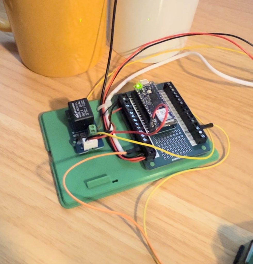
Here's the circuit that does work well
schemeit-project (1)