Please help me with the wiring(Mosfet, resistors) to control a systemair K 200 EC fan with a esp32. FanInput: 0-10VDC,pwm

Were you serious with your consideration of building them? Or was it like a methaper or thought process? or AI? lol.

Finally I tackled your solution a bit. At first it was very confusing, then I went into AI school again, and we went through all different states, and changed stuff around. I finally understood. I am not even finished with all scenarios, also your PWM inputcontrol solution on the fan.

But I will start to comment, before I lose it.
First it's really great to begin to understand at least a bit. It's like understanding only a few words of a language, to suddenly starting to grasp sentences. Feels good.
But I know I am still at the very start, but I will give my opinion, and hopefully get criticized when I say bs.

I will give my understanding of your post.
I will try not to copy AI, but stuff I figured myself.(Also from memory of course)
Lets compare it to ledsyns first iteration, that got improved by AI and me. This one:

Optocoupler is probably always better, because of physical isolation.(crazy whats inside there :rofl:) So lets keep that aside, and focus on both mosfet solutions:

  • Your solution is a low-side-switch.
  • My diagram is a high switch.
  • You have a pull-up transistor(10V-Control), I have a pull-down resistor.(Gate-Source)
  • Your solutions connects the internal controlVoltage(10V) of the fan to the ground, by draining through there. My diagram keeps the fans 10V isolated inside the fan, and drained back to it. So less noise, and more "clean".

-The IRLB8721 is not perfect regarding the 3.3V threshold in the first place. By splitting the MCU high state into two resistors, you reduce voltage on gate roughly about 10%.

(I was also trying to guess the different output heat of both solutions, but I chickened out)
Edit: I think mine should be much lower, since I have technically only one transistor, that only resists when gate is ON. the 2nd one does NOT resists to active energy flow, but is only for risidual voltage on the gate, when MCU is off/low.

-My Diagram has a drawback regarding the 3.3V and the activation threshold of the mosfet. the resistance(Voltage levels) of the control input is higher than the ground. Meaning the delta of gate-source is not 10V but less. Which makes the mosfet harder to switch on.

Not sure what is worse, your 10% losing, or mine.

-also I discovered, that there is a small current in your setup from 10V of the fan, through the 10k to the controlinput if the mosfet is off.
This results in a current, that is depended on the fans control board internal resistance.
-Even a small current, when mosfet is ON, but that could be mitagated by a resistor that has slightly higher resistance than the mosfet when switched on(RDS[on]). chatgpt confirmed it. Feelt pretty good to find out, especially now that I remembered, that people where complaining about dimmer or potentiometer not switching off at 0.
Wow everything gets a bit clearer.

Mine has NOT this leakage(at least not when mosfet is off, but when on, which acts different), but a other big drawback, that could potentially not switch the mosfet on at all.(I am just in the process to understand why) something like voltagedelta is not the full 10V between
.....

-Sure I have not found all pros and cons. And I have at least 30 pages left to read with several AIs, about the discussion about the two solutions.
I am sure there are mistakes in my understanding here. But a bit better than yesterday.

And still haven't even connected the fan to any circuit yet, but feel much safer, tackling the optocoupler later. Still not access to the german systemair optocoupler diagrams, since I forgot my password to that forum :speak_no_evil:

Wow that sounds extremely negative and emotional by you. when did I call it my "friend"?

It is pretty clear because of the physical seperation of the two systems through light(how cool)

And AI did say, that my solution probably does not switch on. And I still not understand what voltagedelta or something like that it means.(Maybe because I high-switch to the control, and not the ground) Still got 30 pages left to read, as said above. I try to go through all in detail.

And I have not even started with the optocoupler yet, even though everything is ready next to me. Maybe I just blindly do it, because I trust you there, so I have at least some practical achivements once in a while. And learn more theory later, maybe with some mosfets and some leds or other stuff, and not my systemair.

So in the end who do you believe me or AI.
I seem to be wasting my time here.

Hey Mr P. I told you from the start, that I trust your opinion the most of them all, including AI.
At least on this topic to be fair. I already stated, I will try your opto 100%, and I trust it blind.
I use use AI to learn. I use several AIs, because I run out of free messages most of the time.
Since yesterday we have written hundreds of pages...you prefer answering all my questions?
Be my personal tutor? Like AI?
I would gladly trade you....
but I guess not :crazy_face:

You aren't even that of a chatterbox to be honest.
That was NOT a critique, but understandable. I am not the only one needing help.
And I already gave you my honest gratitude.
And I am grateful.
But you make me feel guilty when asking AI something, like I would cheat on you :rofl: :see_no_evil:

I hope you did not leave me. :flushed:
I try very hard to find why it is "not safe" I guess. First one was "not working", so it must be safety.
Maybe a resistor to protect the controlinput, maybe a resistor from gate to ground, so when the MCU resets, the mosfet stays off.
Or a fallback diode to protect controlinput, but that is very very likely inside the systemair.
But I don't think you would complain about that. I think it's more SERIOUS :see_no_evil:

There is more info to the controlinput, since I made some measurements:

  • Control to 10V: ~130kΩ
  • Control to GND: ~90kΩ

I = V / R_total = 9.3V / (130kΩ + 90kΩ) ≈ 0.042mA
The 9.3V where measured on the 10V fan supply, with potentiometer disconnected, and fan not spinning.

After knowing the high impedance of the controlinput, do you still have "safety concerns" or was I totally on the wrong path?
Can you shed a bit light into the dark please? :blush:

@quantummagic
Since the builtin potentiometer that you remove for external control is apparently 10K, I would be tempted to replace it with a 10K digital potentiometer controlled by I2C/SPI.

Here is one on a handy breakout board from Adafruit.

I provided you with a safe and simple circuit to control the speed of your fan and you are under no obligation to use it.
To use a MOSFET would require a more complicated circuit and I see no need to even consider using it. If you want a MOSFET design, then maybe another forum member will provide you with one.

Hey Mr P. Great to have you back.
I see where the missunderstanding and your resentment comes from.

I regard your solution as 100% correct and it is what I will end up using, if I don't find anything better for low-rpm(But as you said, it needed to be tested)
Your Solution is my christmas package, and I use the anticipation to learn all other stuff here posted first. Because I wanna learn, as you obviously can tell.
I am NOT trying to find a mosfet solution, and ignore yours :rofl: :joy:

I think it's better to first learn some theory, that I at least got some clue how and why things work, and then I start messing with my systemair. Not the other way around. I thought you realized that all already. Maybe I overestimated you :rofl: :stuck_out_tongue_winking_eye:, or you are not 100% focused on the forum here, what is acceptable and understandable, or or or.
You were as well trying to teach, by checking my knowledge, my maturity(I failed I know), and by not feeding me the answers from the start.
But maybe you really don't know a safe mosfet solution, or maybe it's just too much work.
I don't really know.
But I trust you 100% that you can judge your own knowledge, and you would never suggest me a solution, you are not 99,999% sure is correct. That is a pretty big trust and compliment, to trust a stranger with my 300€.
But as said, I read a lot here. Not so much electronics though..lol.

The solution of ledsyn sounded good, even after two AIs confirmed it(Probably not correct)
And I did not even consider it...no offense bro, don't know you.(If hes still here)

So yeah, I was just learning and creating different scenarios to play through in theory and then check with AI as good as it's possible.
btw: AI is better in programming as in circuits I think.
And it improved dramatically the last half year.
Before they would have trouble identifying and following everything correctly when I post them diagrams, for example my own custom one, where I even flipped the N-channel sign, and made it without knowing any "norms".
In 30 cases, they got only one connection wrong from the diagrams.
They also can spot own mistakes now better. But with electronics, you have to invest some work, and hint them in all directions they must evaluate. Like: check leakages.
When all is checked you easily have several pages, often two much in one promt to reason through all at once, humans also don't work like that.
But still hard to judge for me how useful they are for circuits.
Chatgpt and Claude did even battle it out for several pages, if my diagram is a high-side-switch or low side switch. Until claude suddenly admitted it's blunder to chagpt.

And don't forget that I use free modus, and the models I use are regarded as to have no reason. The paid ones, leave them in the dust.
o3 is better in programming than the chief programmer of openai. His words.
o3 crushed world experts(and expert+AI) in medicine with the most difficult cases of the world...and and and.
I think it would be pretty useful, but that is not even my selling line to you.
And I know you are skeptical, and I should not have started.

Anyway:
I will make your circuit later. I start by testing it with a led first. But as I understood correctly, the opto is so safe, that I cannot do anything wrong basically, when my brain is switched is ON.
And the 10V(9.2V) Signal is the strongest energy source.
And putting that "raw" on controlinput is the worst that can happen.(I think...lol. I should have NOT said that)
But I think the systemair could handle that, makes sense. The high impedence confirmed this further. You even have the 12k resistor, that even takes some current away from the worst case.

So again, not worried, but thankful :sweat_smile: :crazy_face:

I highly recommend this site. They also have video tutorials if you like.
https://www.allaboutcircuits.com/textbook/

Ok interesting. So it would change the workload for the esp32.
Maybe that one is better at low rpm,maybe not. It can output 15,5V max. So not sure the risks involved.
I suspect the opto is safer. But this one is a small computer :stuck_out_tongue_winking_eye:
Interesting to know that it exists.

thx
Only short Videos, but good quality.
Also I always learn with practical projects, that's why I like learning with AI. So I can ask questions back, generate more examples etc. Or like before, think what happens when you change position or value of resistors. And then let AI check it. Focusing on smaller parts, they have high enough accuracy.
I learn the best that way, and is the most fun. When looking up concepts or parts, like n-channel vs p-channel I quickly use google-> wikipedia mostly, and when questions ponder the AI. They are pretty good in grasping your knowledge and identifying YOUR problem or missunderstanding.

So I do not plan to make a studium, but only research and understand the parts I need.
But maybe I check their lessons about resistors later and compare. But this will start instantly with all the math...lol.

Anyway...fine

btw I think you are not emotional/angry about AI, but rather the people using it. And your reflect that back to AI. And I understand, especially for someone like you in that forum here.

Will give you the same range of control that the builtin potentiometer gives.

Perhaps. A premade breakout board is certainly easier than breadboarding a solution.

I suspected that. It think the opto will be fine. Maybe I test the premade digiToAnalog pwm-0-10V converter, seeing all the components on it. The german forum also said opto is good.
I guess, I am at least pretty close to optimum with either of them.

Never thought otherwise :wink: were would the fun be in that?

Btw. workload will not change much, but maybe interesting for higher frequencies, or more reliable via I2C.(I did not ask AI)

Let’s talk about theory.

You want to use a N-MOSFET. (IRLB8721, but hey, a sledgehammer is good enough to kill a mosquito.) The channel between Drain and Source will conduct when the voltage between Gate and Source is high enough.

Let’s talk about the circuit in post #61.

The Source is connected to the input of the fan. The MOSFET will conduct when the gate has a high enough voltage. But: the voltage at the gate can never be higher than the supply voltage of your MCU: 3.3V. You will never be able to send more than 3.3V – Threshold Voltage to the input of the fan.

More theory: voltage dividers.

Definition: a voltage source gives a constant voltage, independent of the current. In the figure above, R1 and R2 form a voltage divider, i1 = i2, so V1 can be calculated by the resistance values of R1 and R2. Adding R3 will draw more current from the voltage source, but it will not change V0, so R3 does not affect V1, does not affect the voltage divider.

The 2 resistors in post #56 are NOT a voltage divider, the 2 resistors in post #61 are.

1 Like

Hello my favorite member of this forum :slight_smile:
You just helped me again, a few hours ago.
I did not forget that thread, or to mark it as solved.
Was just really busy with programming...lol.
It works of course.(did not doubt).
I did experiment a bit with resistors, to lower the RPM, but managed only to shift the "dutyCycle" around. Physically no change. But I can get down to 6% DutyCycle.(Needs more to start of course) Which equals to around 2 rounds per second. Don't think it works any lower. But just in case, you have a trick up the sleeve, don't hold back :wink:

Oh and yesterday I lost a whole day because havn't read the sensors for very long. I think last time when I was still using arduino. I thought I killed them with soldering heat, or my esp-idf program was wrong, or wiring, or GPIOS.?
[(Some just don't work)( I realized I can check all GPIOS Voltage, when all is default, and the ones with 3.3V(0,20,39) 0.06V(38,4) seem to be avoided, or need extra care I guess.]

I checked my soldered cable with 4pin connectors(first in my life :slight_smile: 20 times, all worked.
Then today I realized it could be the cable length(2m)..lol.
Then found your post, put 2x 4.7k in sda and scl, and it worked.
But was not 100% accurate. sudden 2°C jumps sometimes.
But even with my basic understanding, I realized that the output of my esp32 of 3V instead of 3.3V is not helping to make it better...lol.
So sensor it's own 3.3V stable...voila! totally stable. 1hz - 30000hz.
Normal cable.

When not stresstesting, 100hz are totally fine.
Are there downsides going that low, except the obvious ones like delay and bandwidth?
Maybe even put a higher transistor than 4.7k? Since 100hz is 1000 times less than 10000.
So 10x should be safe. 50k?
I am just guessing, but better ask you beforehand.
But not that important. It works perfectly fine.

Maybe I have something to give back to you, or in general to the people here.
I have studied for month now with AI, about different ways of programming and patterns.
But the thing is, I discovered them mostly all by myself.
For example chatgpt mentioned a HAL layer the first time(Hardware Abstraction Layer), I talked "meta" with it.
First week of starting with everything. Arduino, hardware, mcu, esp-idf.

I thought "No no...not that complicated" don't need that. HAL...lol..naaa thx
I ended not only up with one HAL, but several layers of them, without even realizing it's called HAL.

Maybe it would be something for you, or others here. This will be my first publication when done. But not really sure, if there is interest here or in general. But I would think so.
Maybe you can give hint. Because the program is not only for me, but with other users in mind.
Not sure if I should skip that, but it's kinda fun. But would be tragic, if noone would even wanna look..lol

I make it very brief:
As easy to use as arduino, but for esp-idf. All functionality is still there, everything gets basically extended, made easier, and APIs provided. Nothing external used!
Two layers: Tools and myEsp32 Hardware layer.
The user starts fresh with his main.(Everything is hidden away)(Can even switch to other mains with hotkey(for testing, or other stuff)
The user simply has one entry point to all the hardware and tools.
No globals used, everything neat, fast and very easy to use.
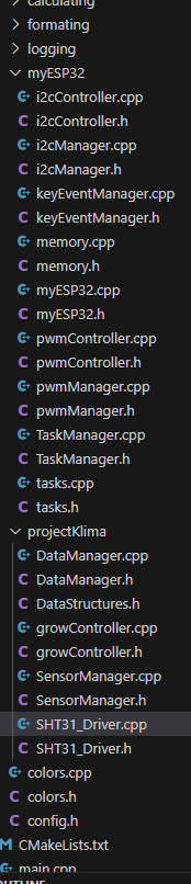
Already a lot of classes:(Don't fit all on screen)

example.

myEsp32 has all physical hardware connections in one place(Before that, everything was in its own Manager, now even easier with the hardware initialization in one place.)

Pwm section:
(GPIO_NUM_16, LEDC_TIMER_0, LEDC_LOW_SPEED_MODE, LEDC_CHANNEL_0, LEDC_TIMER_13_BIT, frequency);

All the user really needs to do is:

pwmGreen = _myEsp32.pwm.get(GPIO_NUM_16);
pwmGreen->setDutyCycle(60);

Everything that could be changed at runtime, and doesn't need hardware rewire is exposed, for hardware rewire see above.

Same goes for i2c, or keyEventsManager for example.
This is all that is needed, to send KeyStrokes to your program.

    _myEsp32.keyEvents.subscribe([](const std::string& data) {
        LOG_INFO("Keystroke: %s", data.c_str());
    });

I may change that, so the syntax will get easier.
Maybe just _myEsp32.keyEvents.subscribe(Myfunction)

This works with no processing power used in the background, when no key is pressed.
Everything is optimized. Not one timecheck in several thousand lines.

or:
_myEsp32.taskManager.createTask(GrowController::task_handleLogic, "GrowControllerTask", 3096, this, 8, &_taskHandle);

You see same syntax as esp-idf.
That was important for me. It's a addition, not a reinterpretation.

Also a logger, similar to ESP_LOG(but better in my opinion so far), that has all the debug modes, but also filtering for files, and or modules.(LOG_ERROR_LOG_INFO, and many more stuff)

All get's filtered out at compile time, that was the big trick here.
The logger gives all to "Output", which is responsible for sending the streams to either serial monitor, file, or bluetooth.

But the user musn't look at all these things, thats the good part.
If someone really want to change buffer size of something, all is in a config file.
though I am not happy with that.
I think I want config file AND top of file where it is used. I already have a idea, but may need to break a rule for that, but it will be better.

Any many more tools, all VERY SIMPLE to use. All is basically ready to go , for anyone trying to try out esp-idf. I have programed everything multiple ways, and understand the pros and cons of every approach pretty well. I have several thousand pages written and read with AI about all these things.

The program is even aware of configurations in sdkconfig. In the end a user would only need his board.json, and is good to go! just need to decide on GPIOS, the rest is childsplay.
Everything is running perfectly on both cores and is really fast. Definitive a case of premature optimization...lol. But I have fun. It's about learning for me. Memory and background.

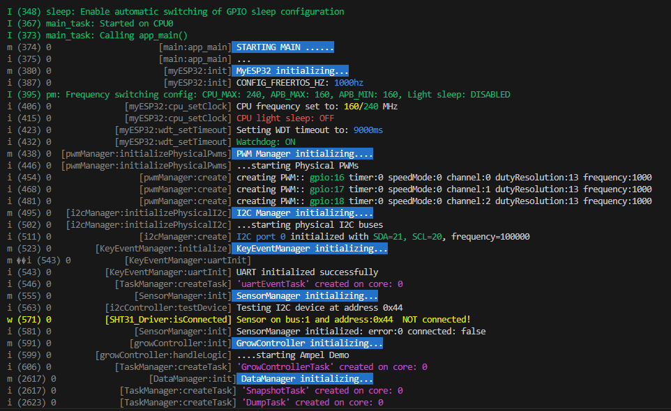
I just made a quick performance test(was done in 5 minutes)
-read all 4 sensors.
-DataManager makes systemsnapshot (pull from the different modules (4 sensor readings from SensorManager, systemerrors(There are no so far), controlData, statuses,) everything I want to safe as data for display.
-DataManager gives the Sensordata from SensorMnager to Growcontroller(simple via snapshot), who controls climate via hardware components of myEsp32.(Growcontrolelr is NOT part of the package, this is user level of course, cause not everybody programs Growcontroller)
Growcontroller gives the snapshot back with the control data of the pwm in the snapshot.
Snapshot in, snapshot out. I was also testing to give only single structures, instead of the whole snapshot, because the modules must not know about the snapshot structure.
But then on the other hand datamanager would get too much responsibility.
It acts as single source of truth for data, and is intended to be in tight loop with the performance hungriest of them all, the display.
But by dataManager just giving the modules the snapshot, we violate SRP principle, but then on the other hand, the modules are so well structured and easy, that this is the best choice. Here easy of use wins vs norms.

DataManager has then one "stream" of information, you can easily follow. Otherwise you need more queues and buffers in the background.
But my solution is even faster, and waaaay simpler. Even simpler than arduino with the "if millis < x" bullshit. All tasks have watchdogs, and nothings gets starved.
The advantages are simplicity,(only vTaskDelay used), no performance impact, and easier time of runtime managing. I think one disadvantage is though, the whole system drift temporal a bit. 5000ms can vary slightly. For performance reasons and easy of use, I have not spwaned a RTOS timer yet, only using ticks.(I guess performance impact is very low, and it can be simple implemented, and the user uses a perfectDelay instead of Delay or something.

The detailed error logging, is very simple done in each module via normal serial logging.
That can also be routed to local storage or network for detailed stuff.

(This is User level now btw. So my program. But I leave a basic working blueprint when making public. DataManger has several Buffers and saves and lazy loads history data from flash/sdCard.)
This is done in binary and aligned in memory. Fslittle.(Oh shit, that is maybe one external tool I used, not sure the definition)
Power outtage during writing to flash or sd card is no problem. All is handled and safe.

-This loop is ALL done 1000 times per second, and the cpu is basically idle!
And all on only ONE core.!! (This was just quick test / Both cores comes next, should straight up work, will see how careful I was.)

I know that I have basically nearly all CPU power left, because everytime the cpu is idle, it switches to performance_counter that increments a counter.(My first tool after the logger(that runs automatic in the background, and you see what takes how much CPU, without writing a single line for it).

I truly love it(People here did not get it's advantage after several pages discussion, so I won't start.(Now have the real arguments)) While all the above is happening 1000 times per second, it still counts to 12.800.000.(13.200.000 is max)
Could make the algorithm count to 40million/s(Have a better one), but that's not the point. So nearly all of the CPU power left.
The dip to 11.438.701 million in the screenshot is because of the long print on screen(tasks(print by pressing tab))
It goes back again afterwards.(Prints every second)
Of course for the user it shows 0-100 CPU, isntead of numbers, or user choice. Or deactivate it.

You can also print tasks or memory stats with hotkeys.
Only so little heap, because I tested 5000 systemsnapshots in memory.
Will add compression as well, so you can even faster, loads weeks of data(one systemsnapshot per second) ultra fast to show on display, or what ever.


Oh in the middle of all, I can even spam keys as much as I want(and print them to screen(printing to serial is slowest of all...lol), like staying on the button to spam it, while also printing tasks and memory, + all other logs. + 1000 times systemsnapshot a second, using it to control, and save all to flash/sdcard.
RTOS-SCORE: 12.437.874(of 13.200.000)..not bad right?

That means I should be able to handle 30 times the load(2 cores)..lol.
Or ONE display..lol(Was really unhappy with fps in arduino hav'nt tried in esp-idf yet, probably need to port)


I have not used any external profiling tools or anything, or even locked at other code..lol.
And I probably won't have to(except display), because doing things fast, but not complicated is not that difficult. I have tested nearly all new concepts as good as I could, and I have a pretty good feeling, what costs what.
Performance was not the main factor, but also ease of use. Kind best of both worlds.
A perfect C/C++ Symbiose :heart_eyes_cat:
After benchamrking the difference of char* and std::string and having done and benchmarked both C/C++ at the start(could not decide which language to focus on) I asked chatgpt:
"Hey digga, would it make sense, to use std::string for transfering, and in the function I decide depending on the usecase if I wanna use char* or std::String inside the function, before returning it as std::String?"
"-Yes of course you can do that, like 90% of people do, that mix both languages"
lol.

The userlevel(My actual growcontroller) will have a demo, how to use super loops, with vTaskDelay only. I have a pretty good concept for that, sure it has a name though.
Splitting everything in tasks makes it harder to overview the flow. But my system combines both, so that the user can use a style even simpler than arduino.

I hope you have even read that, I think you don't like them long posts, but wanted to give you a first impression.
Would love to hear your opinion if you can.
Or anyone else, though I doubt anyone is still here. :sweat_smile:

`

Since the original topic is solved, most people won't look at this post anymore. You should start a new topic in the Showcase subcatagory of the Projects catagory. Describe your new IDE. You will receive plenty of replies. Some will be negative so don't be discouraged.

@quantummagic
you've already copied the same message into at least three threads, two of which it has nothing to do with.
This is a violation of the forum rules

I totally forgot to answer you!!
Your post shocked me to the core....lol. :cold_face:
Very much appreciated. :saluting_face:
I did NOT forgot, that I got so betrayed by AI, thx.

This is shocking...lol.
Several AI got it wrong the same way. Really surprised me, they got that "simple" piece wrong.
But for other things they are really helpful, but as you see, you have to know them and their weaknesses.