Here's the issue: I have a constant-voltage system supplying < 2 VDC to an experimental setup (right now, current draw is very low (milli-amps), but future iterations could scale to be ~10 A), and I would like to use an arduino to reverse the polarity at set intervals of time.
From what I can tell, controlling a 5V DPDT switch with the arduino and a transistor, and using a resistor and diode for protection is probably an OK approach, but I'm not entirely sure how to wire everything together (existing online diagrams seem to be based on a 12 V system using a 12 V motor), and I'm not sure about the sizing of the resistor and diode.
Again, just to be clear, the < 2 VDC simply needs to run through the arduino-controlled DPDT switch, and have the polarity reversed at set intervals.
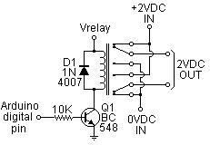
This looks like it should work. One other question: if I were to wire this up on a breadboard, would the negative on the relay coil (labeled Vrelay in your diagram) be connected to the arduino ground?
Here's the issue: I have a constant-voltage system supplying < 2 VDC to an experimental setup (right now, current draw is very low (milli-amps), but future iterations could scale to be ~10 A), and I would like to use an arduino to reverse the polarity at set intervals of time.
From what I can tell, controlling a 5V DPDT switch with the arduino and a transistor, and using a resistor and diode for protection is probably an OK approach, but I'm not entirely sure how to wire everything together (existing online diagrams seem to be based on a 12 V system using a 12 V motor), and I'm not sure about the sizing of the resistor and diode.
Again, just to be clear, the < 2 VDC simply needs to run through the arduino-controlled DPDT switch, and have the polarity reversed at set intervals.
Any help would be much appreciated.
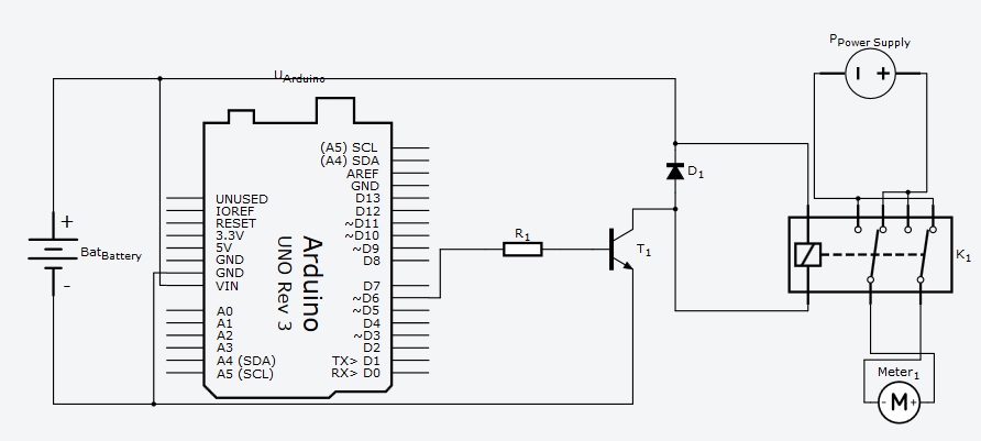
I really have to ask about your constant-voltage power supply. Is the voltage sensing at the terminals of your project, or internal inside the power supply. If internal, will it try to maintain the voltage output while the output circuit is open, during the relay switching time?
If the voltage sensing is at the terminals of your project, you will need to reverse those connections, also.
Thanks for asking. It's not a 4-wire setup, so the voltage sensing is internal to the power supply; therefore, it shouldn't require switching the polarity of anything other than the power supply leads.
rhozzy:
This looks like it should work. One other question: if I were to wire this up on a breadboard, would the negative on the relay coil (labeled Vrelay in your diagram) be connected to the arduino ground?
The point labelled Vrelay is the relay positive voltage, not the negative.
The emitter of the transistor would be connected to Arduino ground. (That's why I used a ground symbol on the emitter.)
Edit: As Larry points out, the relay power supply negative also connects to the same point.
When the Arduino digital pin goes high, the transistor switches the lower side of the relay coil to ground.
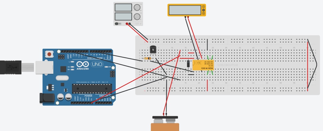
I've attached a breadboard schematic of what I interpreted OldSteve's diagram to mean (I know, I know, the layout's not pretty, but this is just for simulation on Autodesk 123D Circuits). Note that the 9V battery shown as a supply to the arduino will likely just be a wall wart in practice.
I'll note that the code I'm using to run the simulation is supposed to make pin 2 cycle on for 5 seconds, then off for 5 seconds. The problem is, when the simulation starts I am getting -2 V from the DPDT relay (which is OK), but the polarity never switches.
(Note, if I don't put the diode and transistor in, I can get the simulation to properly reverse polarity.)
rhozzy:
I've attached a breadboard schematic of what I interpreted OldSteve's diagram to mean (I know, I know, the layout's not pretty, but this is just for simulation on Autodesk 123D Circuits). Note that the 9V battery shown as a supply to the arduino will likely just be a wall wart in practice.
I'll note that the code I'm using to run the simulation is supposed to make pin 2 cycle on for 5 seconds, then off for 5 seconds. The problem is, when the simulation starts I am getting -2 V from the DPDT relay (which is OK), but the polarity never switches.
(Note, if I don't put the diode and transistor in, I can get the simulation to properly reverse polarity.)
You haven't attached anything. I hope you don't mean a Fritzing.
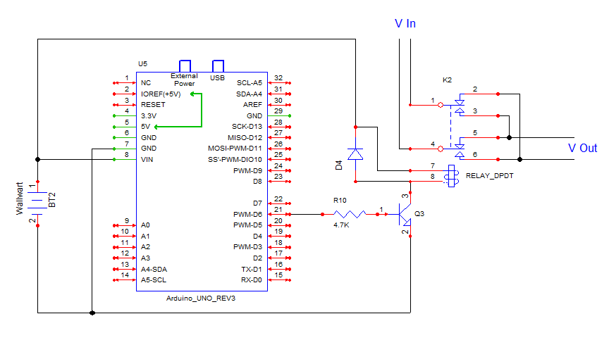
I don't know how you interpreted my diagram to look like that. About the only thing that's OK is the Arduino's connection to the transistor base via the resistor. There's too much elkse wrong to quickly list.
And I hate Fritzing diagrams.
You need to look more closely at the schematic, do some research on how to read them if necessary, then try again.
A couple of points to get you started - You've provided no power supply for the relay. You've connected the relay directly to Arduino ground, the connections to the relay contacts are wrong. The transistor is supposed to switch the 0V side of the relay, not the +V side.
And did I mention, I hate Fritzing diagrams! Learn to read a schematic properly and throw the Fritzing crap in the rubbish where it belongs.
Edit: I guess it's Autodesk, not Fritzing, but it's the same thing. If you're running a simulation, you should be able to trace and fix your errors.