My 'stupid' thinking: there are pins brought out as signals (on headers left and right of MCU module).
OK, I know: when using I2C or SPI their signals come out there (e.g. D12 and D11 now as I2C signals). Those will be "my signals".
But 'stupid' assumption was: "all pins, signals on the MCU headers" I do not 'touch - are free as GPIOs. And I have provided a command to configure all remaining pins/signals as GPIOs (as in or out).
What a big mistake:
I use the wired ETH connection (ETH via breakout board). But two pins/signals are wired directly to the ETH controller. Even provided on MCU module - they are shared with ETH controller.
So, with wired ETH: J2-27 (A2) and J2-75 (A1) are not "usable". If you touch those, e.g. to use as GPIOs or give them another "ALT"ternate function - you will kill your ETH network connection!
BTW: J2-73 (A0) has a bit strange high voltage level (3.08V high and 326mv low). Different as all other pins. So, I assume, even this one might be connected to something else on the board.
Conclusion:
Check the schematics carefully if a pin, signal is really unused. Do not assume (as I did): all populated signals on header pins are free to use. They are NOT.
(they can be connected to internal board components and features).
oh men - even more conflicts on the MCU module pins:
I need SPI1!
But I see some signals are provided twice (two pins with same signal).
Also, some analog pins are identical with digital pins:
Conflict with analog pins (assuming PC2 is also PC2_C -not sure if it is a separate pin: even it is:
functional wise I might "disable" PC2 function when selecting PC2_C!):
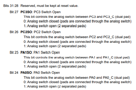
PC2 - PC2_C
PC3 - PC3_C
so, at the end: at least FOUR signals provided on MCU header are duplicated (and conflict with SPI1).
Plus the TWO signals going to ETH controller - 6 of these MCU header pins are not usable.
(Why PC2, PC3 are provided twice? Wasting connectivity)
I thought the same, that every pin on the header is exclusive to the header.
Did you mean J2-77 (A2)?
So P2C and P2C_C are connected to the same channel or where is the problem using A1/A2 and ethernet at the same time?
In the schematics i can't see a connection between P2C_2 and the ethernet controller.
I get the problem with the spi pin.
Working with the portenta is sometimes just such a bad experience.
FYI, PC2 and PC2_C are two different pins on the chip package. Yes, you can connect and disconnect PC2_C (for instance) from PC2.
But if you want to use PC2_C - you need to close the analog switch. But internally, now PC2_C and PC2 pins are connected.
If I need still PC2 digital function - the same signal comes out (or in) on PC2_C. So: if PC2 is needed for a function - the PC2_C becomes unusable (even a different pin, signal on header).
What I mean is just: the header signals are often doubled: even it looks like a different header signal - it is actually the same signal (a waste of available header pins).
The PC2_C (and other Pxx_C signals) are only usable as ADC input signals (analog switch remains open). So, you can never use PC2_C as another digital signal. If so: analog switch closed but now PC2_C is the same as PC2.
Actually, clearly to see: J2-77 is just ADC_A3 - no other digital function available on it.
It was my wrong assumption I could use PC2_C as a digital signal, e.g. as an output: yes, it works with analog switch closed, but than this digital signal is identical to PC2.