It is very easy to "kill", brick your Portenta H7 board. Something wrong on a flashed FW - and it is dead forever.
FYI:
Portenta H7 has a PMIC chip. It is set to generate 3.1V core VDD. But I saw also on my board: core VDD is below 3.0V. ST-LINK debugger measures as 2.94V.
BTW: I was not able to increase the VDD core voltage, e.g. to 3.3V (as nominal). Max. seems to be 3.1V but potentially even lower!
Arduino sketches and LIB run the MCU core with just 450 MHz (not nominal 480 MHz).
Meanwhile an obvious reason: with 3.0V core VDD - MCU cannot do with 480 MHz.
So,
if you try to configure for 480 MHz - be very carful: if your PMIC does not provide 3.1V, e.g. as in my case below 3.0V - MCU will not run
the same if you play with FLASH_LATENCY_x : if not enough wait cycles - MCU is dead. (flash gets slower with lower voltage)
My impression: if you were successful on flashing a new FW but with fast MCU core clock, lower FLASH_LATENCY - the next time you CANNOT flash anymore any new, corrected FW:
My ST-LINK was not able to connect to the target. Potentially, the core VDD voltage was too low (2.94V). And the MCU has crashed and blocked the system (due to booting with 480 MHz).
The debugger could not find target, it could not connect to Portenta H7 MCU and not possible to flash a "corrected FW".
The only solution was: remove the ETH cable: un-power the ETH controller: now, luckily, the debugger could see and flash again (assuming right at the edge with low voltage).
So, it tells me this:
Even Arduino configures just 450 MHz - do not make it faster! 480 MHz with just 3.0V and even lower - will crash the MCU (and debugger might see a blocked system - unable to connect)
If you have a board like me, where the PMIC does not generate (intended) 3.1V for MCU core, just below 3.0V - your debugger might not find the target. You have to find how to let increase the voltage a bit again, e.g. as in my case: remove the ETH cable.
Do not try try to overclock the MCU: with 3.0V even larger as 450 MHz is already an over-clocking.
If you have flashed ONCE such a FW which results in a crash right after reset or power-up - you might have serious trouble to get the board back (ST-LINK debugger does not work).
If you use still the Bootloader (I don't) - you might be fine (it assumes 450 MHz and lower voltage and should still flash).
Just if you overwrite bootloader and something is "out of spec. region" - it is dead - forever (even not able to write back the Bootloader).
You might end up with a board which is potentially broken forever!
So, do not try to overclock MCU, do not rip out the Bootloader ...
Yes, PMIC: this MC34PF1550A4EP - this NXP PF1550.
Do you know how to trim it for 3.3V instead of 3.1V?
Even datasheet has settings - it does not work to get it larger as 3.1V
I have measured with a professional volt meter.
And the ST-LINK shows the Core VDD (it has a sense on debug connector, to know if the board is powered and what is core voltage - used to configure the debug signals accordingly).
Sorry, don't have a Portenta H7 and I had not heard before of such a Power Management chip and I don't understand the registers for the I2C interface.
I replied because it seems a unwanted situation and I wanted more information.
How is the VREFDDR reference ?
In the datasheet, page 134 and 135, they are specific.
Thank you.
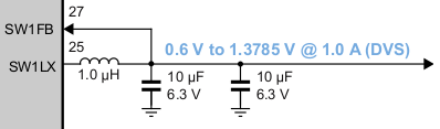
The schematics of Portenta H7 matches with the PF1550 datasheet. The inductors have the same inductivity.
I would assume: Portenta H7 draws a bit more current which lowers the voltage.
Never mind: it looks like 3.1V is OK - as long as we do not overclock the MCU.
I can confirm a bit more: with 3.1V (or even lower as 3.0V as in my case) - you CANNOT make the MCU clock faster as 450 MHz:
I tried to use the Backup SRAM (via D3 domain and AXI interface). When I run the MCU with faster as 450 MHz - on 3.0V - the bus fabric generates errors when accessing Backup SRAM, in a random way: sometimes I get a HardFault_Handler called when accessing Backup SDRAM.
With 450 MHz and slower it is fine.
So, with 3.1V or even 3.0V MCU core VDD - faster as 450 MHz is already "overclocking".
The lower the core VDD - the lower the clock has to be (like "DVFS" = Dynamic Voltage Frequency Scaling).
Is there a datasheet/table for DVFS on STM32H747 MCU?
CubeMX tools tells me: 408 MHz, 3.0V - we need V0S0: Scale0.
So, very important to configure:
Let me post here my latest clock config: system_clock_override.c (11.8 KB)
This one is corrected for voltage scaling, PLL voltage range.
ATT: check it: it sets 490 MHz core clock.
I doubt if the 2.94V is a problem. I accidentally just bricked my Portenta again. I hooked up the SCL/SDA of an Arduino Uno to the SCL/SDA at I2C1 on the Portenta breakout board, ran my program and got it back to 2.94V. But I was unable to get connection.
Re-reading my instructions in post #6 of that thread, I moved the dip switches and double-clicked on the breakout board, only then I was able to connect STM32 Cube Programmer. After disconnecting it I could burn the boot loader from the Arduino GUI and everything was good again. I don't know why the dip switches must be used (it was trial and error and there probably is a good reason for it) but in your case, next time it happens try doing the same. I broke and restored my board deliberately several times this way and it has always worked.
Cool.
Yes, using the DIP switches might help. One is BOOT mode: if this is changed - the MCU tries to boot from a different address. Potentially, it finds another piece of code there and gets out of the "stucked" mode.
My experiences with the board when bricked:
use another board to program the PIC via I2C, try afterwards if debugger connects (do not reset the Portenta board). Maybe, disable "reset when connecting" or try different modes on debugger:
Sometimes, I have to select "connect in power down mode".
This link provides a full explanation why the BOOT dip switch is required - it puts the Portenta in DFU mode (based on an STM32-internal boot loader that allows bricked systems to come back to life). This suggests that, to get a bricked Portenta working again, apply 3V3 from an external system, set the BOOT switch to the DFU mode, download the boot loader. Note that this forum link also discusses it - although it adds the PMIC programming into the code being launched as opposed to burning the Portenta boot loader and rebooting.
Hi henksb
you are so great!
This BOOT bit option is really nice: I was able to recover a broken Portenta H7 board - no need for an external debugger. So cool.
Here the procedure I did:
if orange LED is on (means: PMIC on board not configured - no power for MCU) - you need external I2C master device (e.g. another Portenta H7 board providing I2C master read/write)
connect the I2C between broken Portenta H7 - the I2C1 (the PMIC I2C bus) and working Portenta H7 as I2C master - the I2C0 on silk screen (user I2C, actually as MCU I2C3)
write the PMIC registers in broken board, from working Portenta H7 as I2C master
Now, the power should be back.
Now:
Have a second USB cable: as USB-A from Portenta breakout board (this user USB connector) to host (in addition to USB-C used as power)
change the BOOT DIP switch and press reset
start the dft-util.exe tool (with proper USB IDs) and flash any FW, even the original Arduino bootloader
change back the BOOT DIP switch and press reset - now the board should boot and run the new flashed FW (bootloader).
So cool. Thank you.
I think, I will create a doc and separate thread.
Details
STM MCU has a pin as BOOT: if it set high - it boots the pre-programmed STM bootloader. If low: it boots in the normal way (your FW). So, BOOT DIP switch will change to boot the STM bootloader (hard-coded).
This STM bootloader has different options for input (connection to host, e.g. UART, SPI and even USB FS mode).
The good thing: the Portenta H7 breakout board has this User USB connector (as USB-A, in addition to the USB-C for power and Arduino bootloader, UART etc.). The pins for this USB FS are correct!!! So, the STM internal bootloader works.
The dft-util.exe works and sees this STM bootloader (with BOOT DIP switch changed, reset done). Potentially, also the STM32CubeProgrammer could see this STM bootloader running.
So, you have an option to flash back any stuff on internal FLASH memory, e.g. the Arduino bootloader, your FW etc.
Just:
if board is "so bricked" that it does not have power - the orange LED on, no voltage on pins, external debugger cannot connect (power is 0.02V) - you have to use an external I2C master device and program the PMIC via I2C first (before doing this above procedure, but w/o to power-cycle the board).
Thanks Tjaekel for nice words. Your procedure looks much more advanced than mine, but I'll take the credit if it led to your procedure. Just to confirm, I followed the above suggestion that I made, which is arguably crude and simple: (1) Move both dip switches away from "Arduino Pro", (2) apply 3.3V from an Arduino Uno to the Portenta 3V3 pin, double-click the ON switch on the breakout board and I could burn the boot loader from the Arduino interface. No PMIC programmer needed. And I was so proud of my little DIY PMIC programmer.
All fine. Does it mean: you have your own DIY PMIC programmer (as an I2C master to configure the PMIC from external)?
Both are not needed: one is BOOT, the other BT_SEL, but it does not hurt.
The ON switch: I think pressing 1x is enough - it is the PWRON signal on PMIC, which might "boot" and reset the MCU. I guess, pressing RESET might work as well.
'
The STM bootloader in chip comes up with BOOT set to high and a USB-A cable connected works to flash all again, also Arduino bootloader.
The "problem" for people is just: if PMIC is not configured, no power, the orange LED is on - this is the tricky part to bring board alive again.
Never mind, I think we both use the same procedure.
Great job. Thank you again for the great advice having this option.
All fine. Does it mean: you have your own DIY PMIC programmer (as an I2C master to configure the PMIC from external)?
Yes, just an Arduino Uno hooked up to the I2C as discussed in this "Portenta Bircked" thread . It had 2 tables to program the PMIC with, one based on your posts, another based on the link I included earlier in this thread (based on the boot loader source code so probably more correct). Both versions work, you can switch by commenting/uncommenting 2 lines.
I wish there had been clear and easy to find instructions somewhere that tells people who used STM32CubeIDE and bricked their board to recover. It seems like almost anyone who tries that, runs into this problem.