Like a potentiometer. Or should I replace the batteries with a different power source for example a 12V DC power adaptor?
between what parameters?
What frequency and PWM mode are you using? the comment isnt really very helpful.
Why does no-one use a data rate that belongs in this millennium?
Did you remove the LED?
How is the Arduino powered?
Yeah I removed the LED. The Arduino is powered by a 12V DC power adaptor.
It' not an efficient circuit but I would expect it to go about 4 hours before the batteries dropped to 8V.
You can use two 12V adaptors to power the circuit. You connect them the same way you connect the batteries. The positive of one connects to the negative of the other and that is the ground point.
Thanks, I'll try that out.
I connected the potentiostat to a three-cell electrode composed of Nickel Foam(WE), saturated calomel electrode (RE), and Graphite (CE). I ran 4 different trials and the results are not reproducible and there is a lot of noise. What could be the possible cause of this?


Noisy power supplies, that's why batteries are recommended.
If you still have it on a solderless breadboard, it will pick up a lot of noise.
If the wires to the cell are not shielded it will pick up noise.
See how it is done in the original paper, nice and neat.
In the original paper they used platinum and Ag/AgCl for electrodes.
1 Like
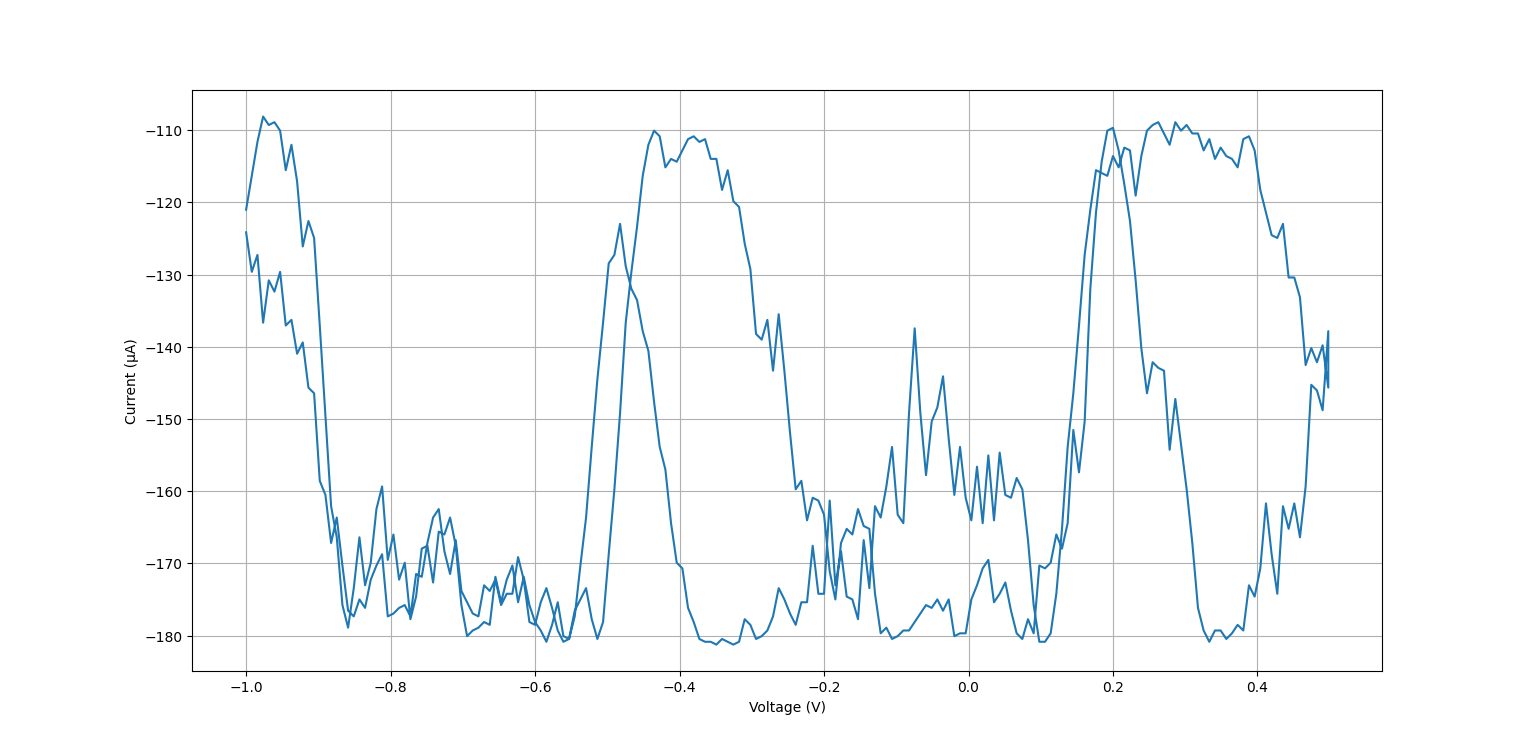
I see there is a super sharp transition an then it saturates.
The circuit is super simple, but need some manual ajustment ( if values are outside limits ).
Try reducing the 12K resistor in the output I/V converter ( 2 or 4 times or more ) until the output does not saturate
( also you could reduce the span of the pwm, but that also reduces the number of samples, but also make the test faster )
To reduce noise you need a 'proper circuit', the breadboard is ok for testing only, and a proper operational amplifier, the lm324 is a 'no quality' amplifier
Thank you so much. I tried doing that yesterday and got these results.

However, today I'm getting these results even though I did not make any changes to the circuit.

Could it be due to connection problems?
Yes I'd say yes, as output is bouncing high and low so fast.
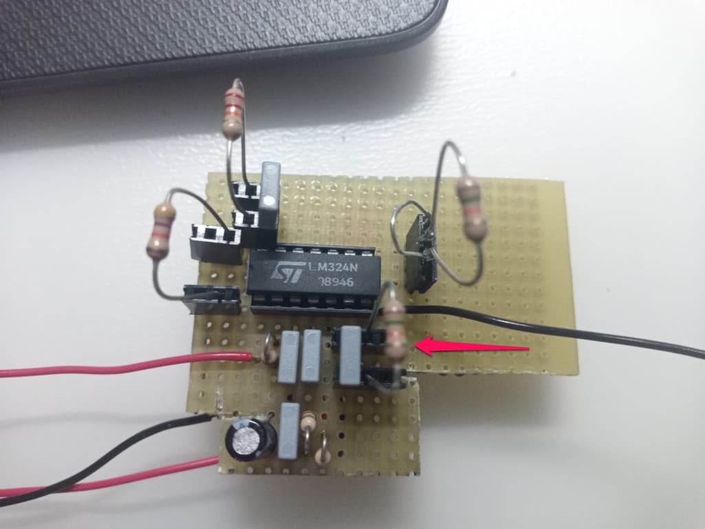
As said the breadbord is not reliable, you can solder the components on a small perforated board, I mounted a few r and c on sockets ( to be able to change values without problem )
You could use a similar system ( just for the R on the output I/V converter ), see image
Doing this you can also replace the lm324 with a more 'serious amplifier'
I generally use TS922 ( which is dual op amp ) for similar tasks.
TS924 is the quad op amp version ( but I think you'll have an hard time finding in dual in line package, as the package is considered obsolete )
I see digikey has MPC6004 and MPC6274 in dil package ( never used but seems ok )
These are low voltage ( max 6V ) so you have to use the circuit I uploaded and power at 5V
See post #28 and the original paper given in post #10
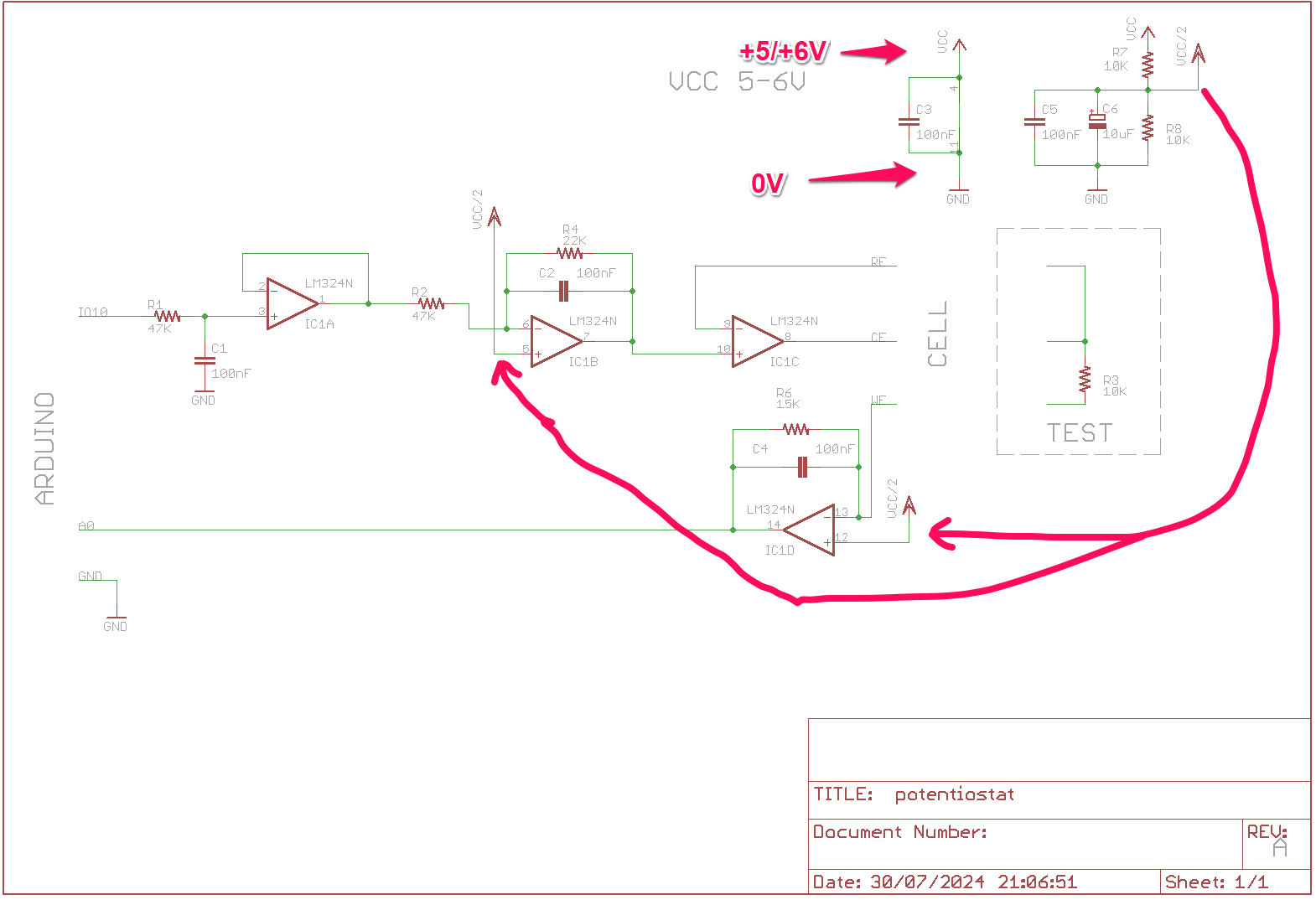
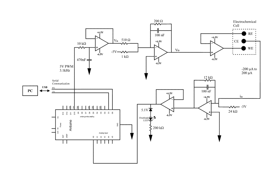
Thank you so much. I'm trying to construct your circuit. In your circuit diagram what is the difference between VCC and VCC/2, and are you powering the amplifier using VCC?
Yes, the circuit is powered via vcc.
The vcc/2 is derived by the 2 resistor divider R7 and R8 and is used to bias the non inverting inputs.
If you are using the lm324, power vcc at 6V or 6.5V and don't need any protection on the input of the arduino a/d.
If you are using one of the rail to rail opamp proposed, power vcc at 5V ( also no protection needed )
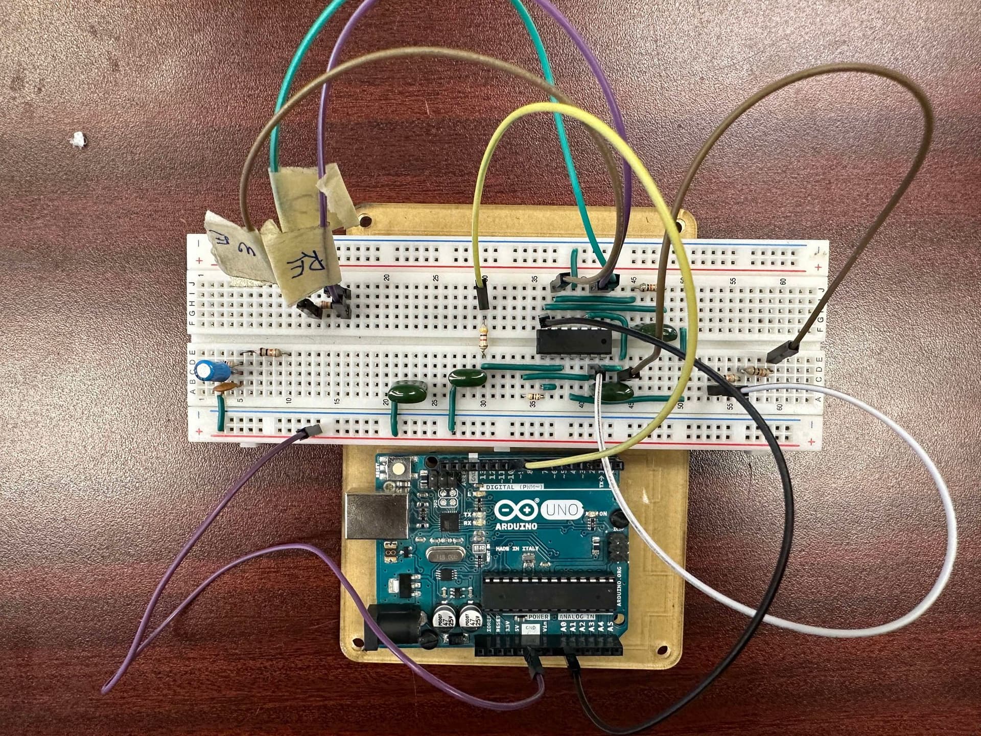
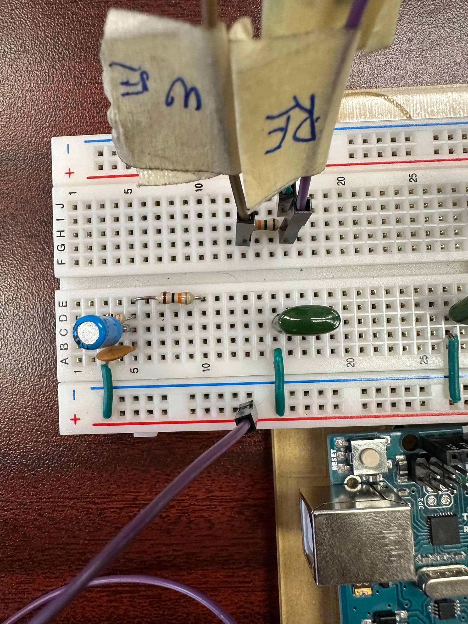
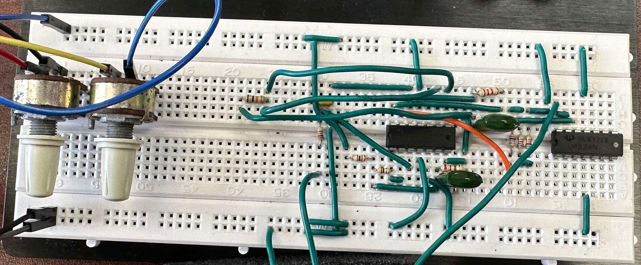
Sorry, I'm having trouble understanding how to wire vcc and vcc/2 in your circuit diagram, as well as how to wire the power source for the amplifier since it needs to be powered with both a positive and negative voltage. This is what I have so far:
You need only a single power supply of 5V or 6V ( if you are using lm324 use 6V ).
Connect the power supply between vcc and gnd ( the C3 shoud be connected to the power pins of the opamp, across the ic, shortest wire ).
Vcc/2 is derived by the two resistors, simply connect the 3 points marked vcc/2 together ( no need for dual supply, opamps are single supply, this derived vcc/2 make them working using the whole voltage span ).
I tried building this circuit and got these results when testing with a 10k resistor.
I thoroughly checked if there were any connection problems and I couldn't find any. Could there be something wrong with how I wired C3 or the vcc/2 wiring? I used a 6V DC power adapter to power the circuit.

What is THIS circuit. Please provide a schematic
Not sure, but seeing as the curve is 'nervous' and not repeatable I guess there is some wire not making good/stable contact.
In the next days I'm going to order new pcbs, I can add a 'potentiostat' circuit, so I can send it to you already assembled an tested ( but it will take 3-4 weeks ) if you need.
I constructed this circuit:
The circuit is powered by two 9V DC power supplies, with the voltage adjusted via potentiometers to set the positive and negative terminals to 6.5 volts as specified in the circuit diagram. However, the result observed is a constant ADC value of 1023, instead of the expected linear increase.