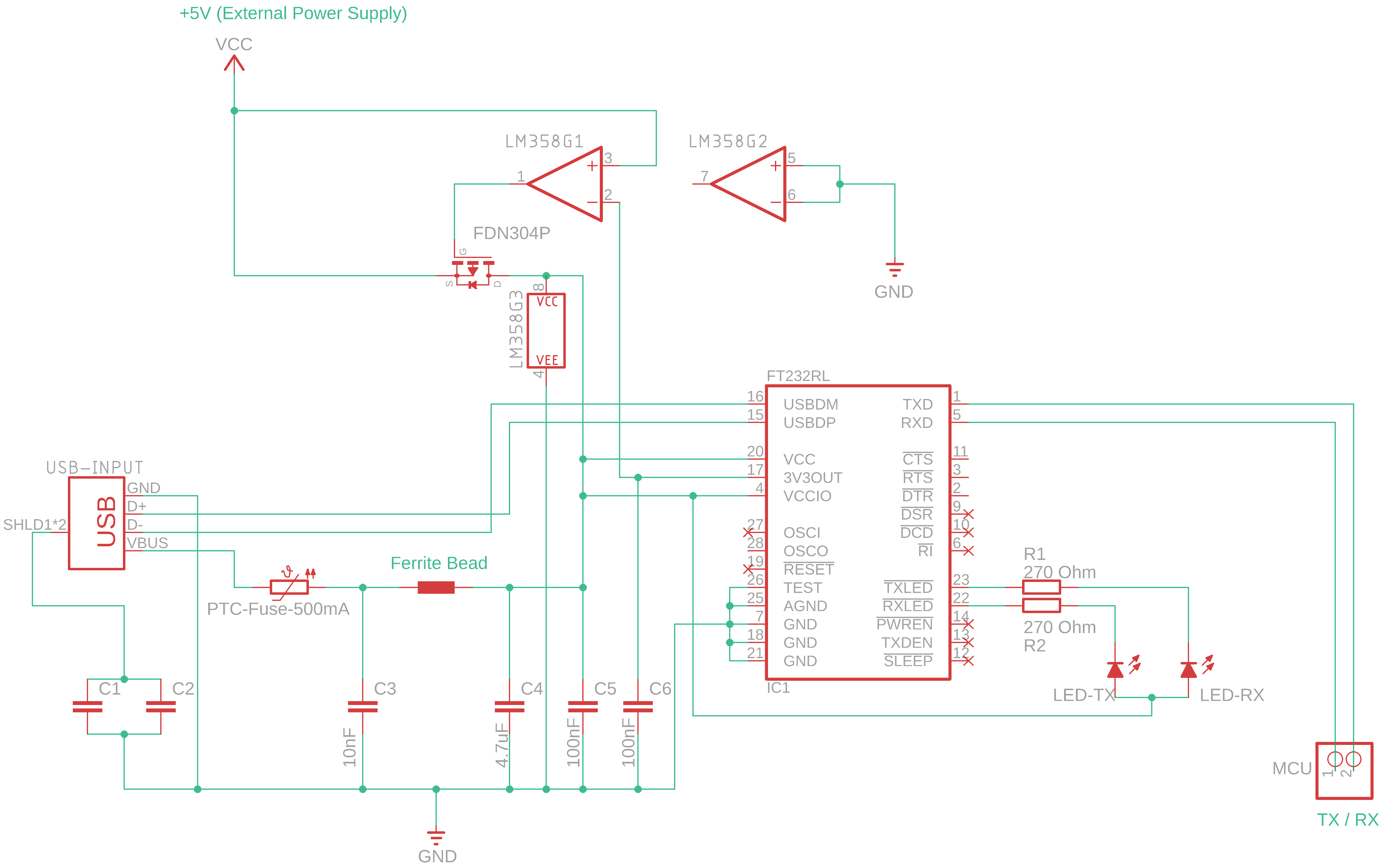
I am currently working on an evaluation board for the ATMega-644, and want to use an FTDI to communicate with it. The board will be powered by both USB and an external power supply. I mostly stuck to the Arduino UNO concerning the power switching wiring. Attached is the corresponding excerpt of my schematic. The capacitors C1 and C2 are only used if there's an issue with the USB-Shield.
This is my first time working on a wiring like this and I am wondering whether I made a mistake that needs to be corrected before etching.
Oh, i missed something! The reference voltage of the power supply has to be measured of course in such a way that the USB voltage does not cause any feedback to the comperator and the transistor does not switch permanently.
I have found a datasheet for the LM358 that has dispelled my concerns. It describes the arrangement of the unused OP in my layout as potentially harmful. The correct wiring is now clear to me. Thanks anyway!