Thank you, I understand the issue now. I've watched the video, that's a good find, thanks. I also decided to ask about the problems you've highlighted on Adafruit's forums hoping to get a response from Adafruit support (which I did) as they should hopefully know their own hardware fairly well. The responses I got are:
10K pullups are on the 'weak' side. So combining several in parallel is usually possible. The practical limit depends on the strength of the GPIO pins of the processor in use, as well as the electrical characteristics of the actual bus wiring.
Most processors can handle at least 3 or 4 sets of 10K pullups. Much more than that can start to cause problems. This can be addressed by removing the pullups from some of the boards.
All of Adafruit's videos and descriptions say how you can connect up to 8 displays (0x70 to 0x77) and that they're designed to be plug and play, so I was hoping they would say they've implemented a simple solution such as cutting a trace to disconnect the pullup resistors. But unfortunately not. I then asked about the multiplexor and got the following response:
The multiplexer effectively creates up to 8 independent buses. In addition to providing a separate address space, these buses are electrically independent as well, so it could be used to isolate smaller groups of devices to minimize the effects of the combined pullups, as well as the total length of each bus.
The downside is that there is some additional software overhead in that you need to explicitly select a channel on the multiplexer before you can communicate with the device(s) connected to that channel.
20cm of bus length in itself is not a problem. But you need to consider the combined length of all bus segments. At normal bus speeds, a total bus length up to about 1 meter is usually workable.
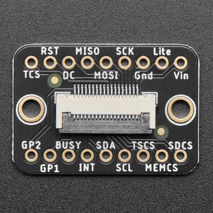
The comment about the 20cm bus length was because I mentioned using a 20cm FPC ribbon cable with breakouts to get the second BME280 sensor inside the server cabinet through the removeable side panel. I've read that I2C is designed for short bus lengths so wanted to check that too.
Not sure if any of this helps at all? But it sounds like the multiplexor is definitely a good option. Where does this leave me with voltage and current draw? I assume it would still be best to power them direct from the USB and not from the ESP32?
For the displays, Adafruit's website says the following:
You can use these with a 3.3v or 5v microcontroller. Just connect the VCC+ pin is the same voltage as the logic on your microcontroller.
But then a few lines later says this:
Connect VCC+ to power - 5V is best but 3V also seems to work for 3V microcontrollers.
"seems to work" doesn't exactly fill you with confidence 

