I'm planning my first project which is a temperature monitor for a server room and server cabinet. I would like to use two BME280 sensors with four 4 digit, 7 segment displays (to show temperature and humidity from each sensor), plus 3 LED's for status and 3 push buttons.
I'm going to be using a DFRobot FireBeetle 2 (ESP32-WROOM-32E) as I want to use the WiFi to send temperature alerts via Telegram. I'm trying to work out if I can safely power everything from this board using a 5V USB power adapter.
As you would expect for red LED's Adafruit list the power consumption for the segment display as "(7 segments + 1 dot) = 8 x 20mA = 160 mA". So, if I was to light the whole thing (I.e. 8.8.8.8 - which I won't need to do) it would consume 640mA per display, giving a max of 2,560mA. The max number of segments I would use would probably be something like this (This is high for an air conditioned room, but going for worst case for if the aircon failed etc.):
I'm struggling to find any figures for the Adafruit BME280 module, but I don't think it uses much as I've read the BME280 itself uses less than 1mA.
Three additional status LEDs = 60mA
Total = 1,740 mA + 2 * BME280
I'm also struggling to find the max current which can be output by the 3v3 and VCC pins of the FireBeetle 2, but I've got a feeling this is too much? Even if I drop to two displays and cycle between temperature and humidity, I'd still be using up to 960 + 60 + (2 * BME280) = 1020+mA.
I find it hard to believe that 20mA per segment would be needed, particularly with modern efficient displays. But if the driver chip does that, there may not be much you can do about it. I would hope you can find someone who has one of these backpack displays who could measure the actual current draw when set to an esily viewable brightness. Perhaps 20mA is just the maximum, which you would never need.
From what I've seen most red LED specs state that the max current is 20mA and I think I usually see a recommended of around 16 to 18mA. I've never tried powering one with less, but might give that a go. The segment display I'm looking at does have multiple brightness levels so I could reduce the power consumption by reducing the brightness quite easily. The problem is I can't work out what the consumption will be at lower levels prior to purchasing, and as this is a project for work I have to prepare a quote for the whole thing and can't keep buying and changing parts etc. I've looked for reviews on YouTube and haven't found anything which measures the current so far. I will have a search elsewhere when too I have time.
@noobmastha I had a look at the TM1637, but the one I saw doesn't have any decimal points and doesn't have any way to change the I2C address. Thank you though.
I'm wondering if it would be best to grab a 5V 3A USB wall adapter with a USB breakout board and power the segment displays directly from that instead of the ESP32's pins. What are your thoughts on this? I would need to do more research as I haven't used a separate power source before. Would I need any additional parts (E.g. a voltage regulator?) or can I just connect them straight to it? I believe the ESP and displays need to share ground, but if I power both from the same adapter I assume that would cover it? If not I can connect the GND pin of the ESP to the GND pin of the USB breakout also.
Absolutely. You would not want to run this kind of current through the ESP module. And there's no need to. As you say, just power the ESP and the displays separately from the same power brick, with a common ground for everything. And I would think 3A would be more than enough. I don't think you would need a regulator. Anything with a USB socket on it should be pretty close to 5V. And the ESP32 being a 3.3V device, it will have its own 3.3V regulator on the module.
Have we talked about the I2C lines? It looks like you will have a voltage difference that may require translation. Also, do the displays have pullup resistors on SDA and SCL? If they do, you may need to remove all but one set. Do we have a schematic for the Adafruit display? What ESP32 module are you using?
Thanks for your reply. The voltage difference didn’t even cross my mind. Here is the schematic for the Adafruit I2C backpack on the segment displays. Looks to me like there are 10k pull-up resistors on SDA and SCL
I’m posting from my phone and couldn’t get a decent screenshot but if you don’t want to click the link I can post an image when I’m back at my computer tomorrow. I also plan to use 2 x Adafruit BME280 sensors via I2C (addresses can be 0x76 and 0x77). The displays can be 0x70 to 0x77 if I remember correctly.
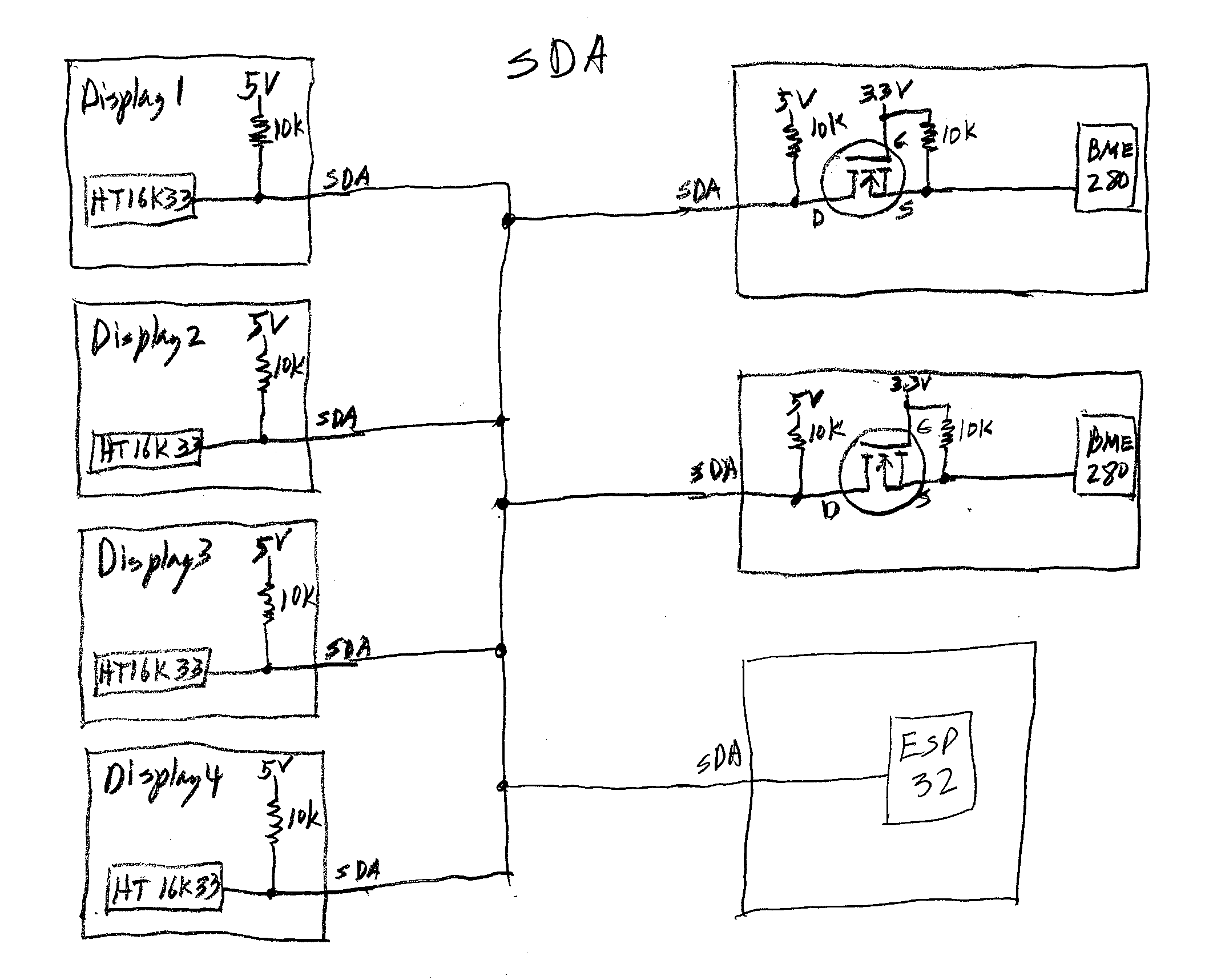
It turns out that the Adafruit BME280 sensor modules have level shifting circuits built in. So you would have two such circuits and four display modules, each with their own pullup resistors. I'm gonna have to draw this out. It's very complicated.
One thing that would simplify this a lot is if the ESP I2C pins are 5V tolerant. The datasheet says they aren't, but there's a lot of discussion online that says they are. Do we have anyone here with experience on this point?
I agree that the displays appear to have 10K pullup resistors. But I don't see any on the ESP32 schematic.
Really appreciate the help. Trust me to pick something complicated lol. I originally thought of using 4 standard segment displays with shift registers (e.g. 4 x 74HC595) but then found out about daisy chaining them to keep the pin count down which is an added complication for me to figure out. Plus I'd need to use a load of resistors and wires/traces but I'm not planning to get a PCB printed, I would need to create something on perf/proto board and try to cram it all into a 3D printed enclosure with a max print area of 140 x 140 x 140mm.
I thought I was simplifying things by opting for a more expensive pre-made I2C display and chose Adafruit's because it has the adjustable addresses.
There are a total of six 10K pullup resistors to 5V, plus two 10K resistors to 3.3V. In effect they are all in parallel. The typical "strong" pullup for I2C is 4.7K. But this is way stronger. The result is that whichever chip is driving the line has to sink a lot of current to bring the line low. I figure it would be 3.66mA, versus 1.06mA for the typical single 4.7K pullup. I don't know whether these chips can do that. And this still leaves the ESP32 pin unshifted, which may or may not work.
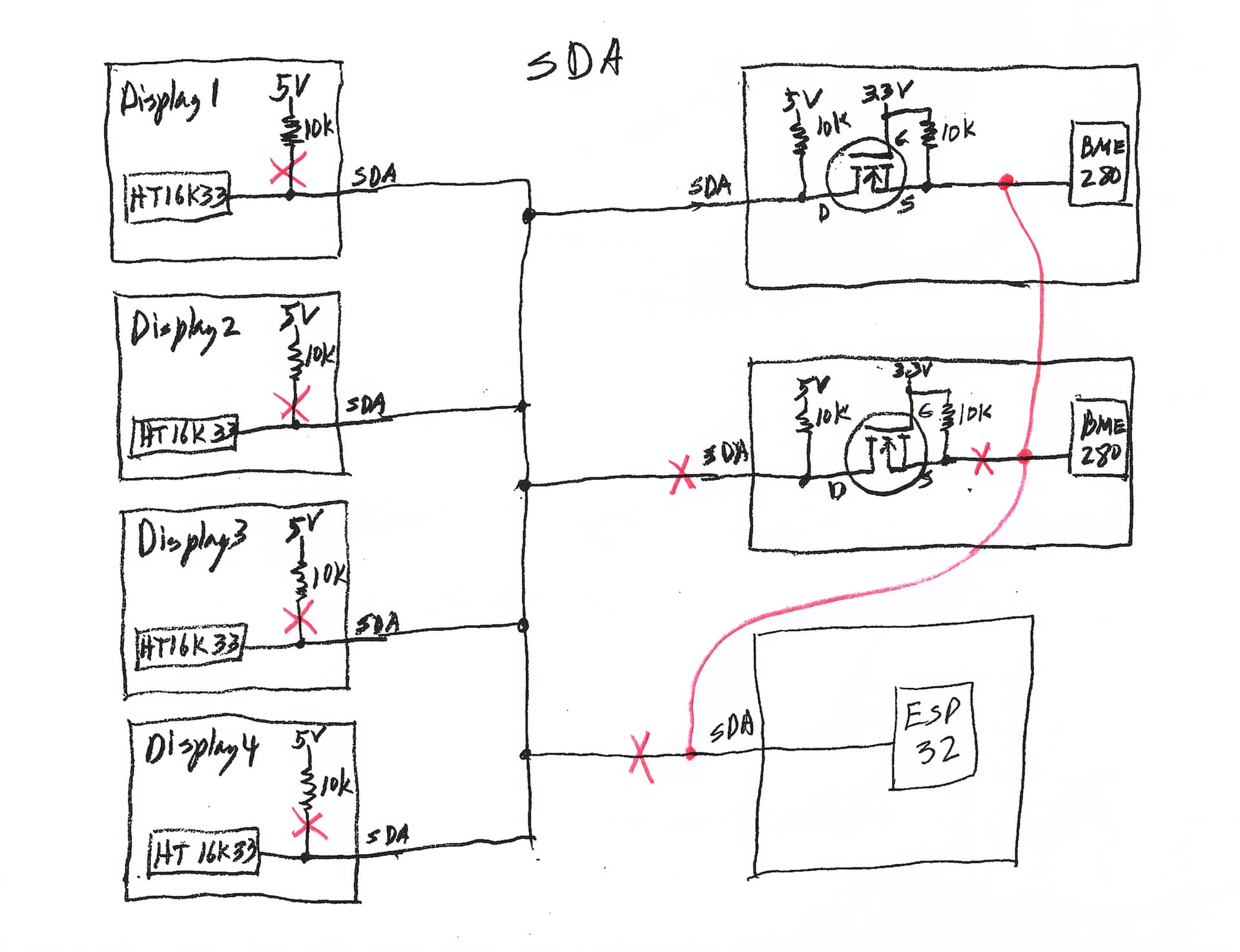
All you really need is one 10K pullup to 5V and one 10K pullup to 3.3V, resulting of 0.83mA when pulled low. The changes shown below in red would be needed to achieve that.
I don't know whether those changes would be practical on these boards - just physically being able to do it with all the small SMD stuff.
There are other BME280 modules online which don't have the 3.3V regulator or the level shifting circuits. They just have pullup resistors which should be easy to remove. They would have to be powered with 3.3V, which could probably be done from ESP32 GPIO pins. But you would still need one level shifter each for SDA and SCL, which would require one dual BSS138 chip. And you would still need to disconnect three of the four pullups on each line on the display modules.
So it turns out that the I2C addressing may work out, and the pullups can work too, but require some thought and rework of the modules. Anyway, I think you have more work to do in settling on the final circuit. And you might want to consider how many displays you really need.
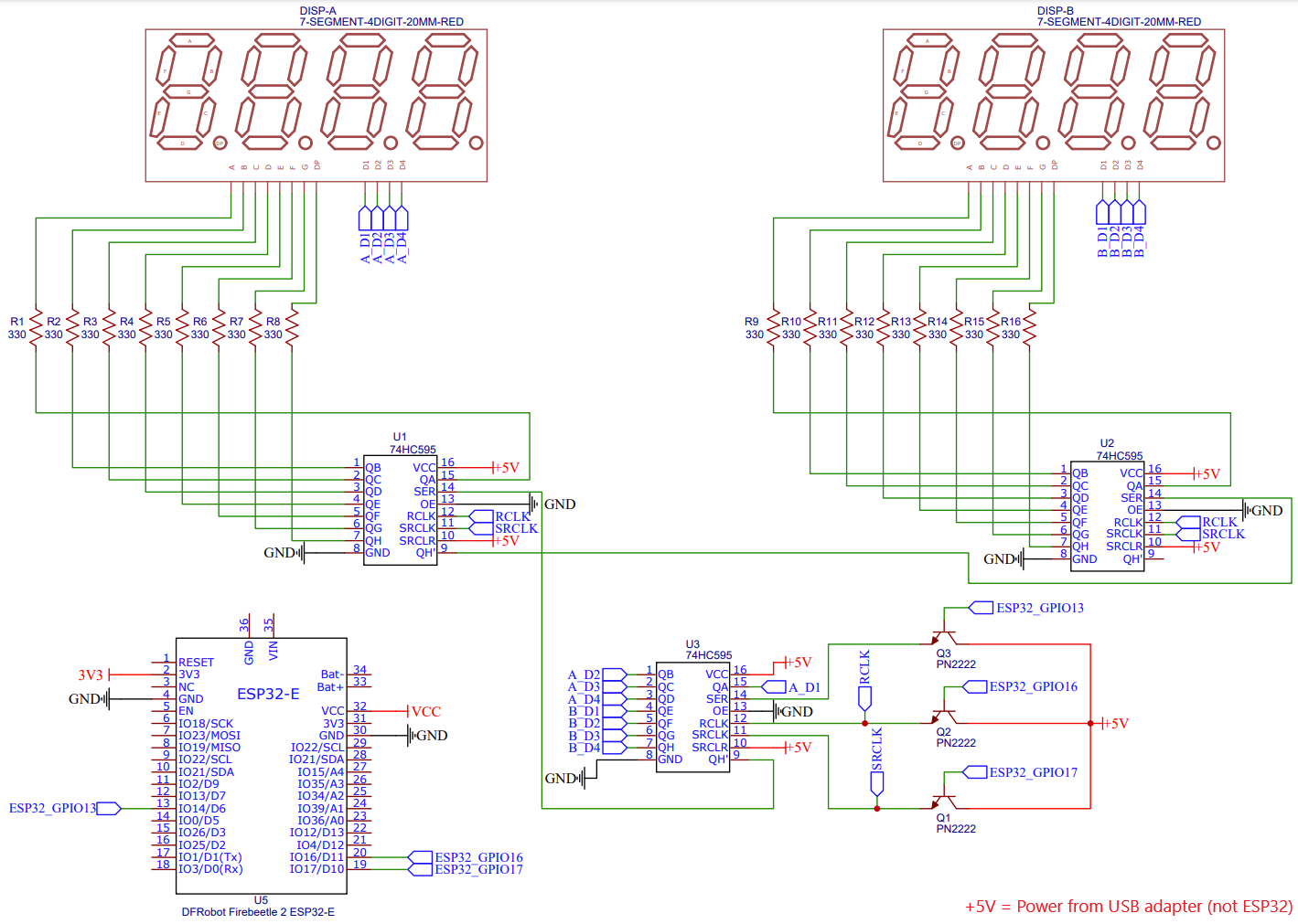
Thank you very much for taking the time to put that together. As you pointed out, making these changes is probably not feasible. So going back to my original thoughts of using shift registers, would something like this work? I'm not sure if I would need resistors for the digit pins on the display (D1 to D4) or for the clock and latch pins on the 74HC595.
I've dropped down to 2 displays to simplify things, but my theory is to push 3 bytes to the serial input and then set the latch pin high. This way I believe I can control which digits and segments are lit using just 3 GPIO's on the ESP32. If I've implemented the transistors correctly I'm hoping this will resolve the issue of using a different voltage. The 5V would be supplied via a USB breakout board which I could then connect back to a second USB cable to power the ESP32.
I would still need to add the two BME280's via I2C at 3.3V, some buttons, single LED's and possibly a water level sensor of some sort which I think is achievable with the remaining pins. If this will work I think my main challenge will be fitting it all in a 3D printed case with through hole components
I'm not sure the 595 can be used for the common cathode or anode. You should look at the datasheet for the maximum current on any one pin, and the maximum current through Vcc or GND. Also, this setup would only let you light up one of the four digits at a time. Are you planning to multiplex them?
Have you considered using an LCD display? It wouldn't be visible across the room, but you could have a 4 line by 20 character display using I2C, and get all the information on there at once. I don't know if this one is any good, but it's the kind of thing that might work. I don't know if they come in 3.3V versions.
I think you are not going to want the Adafruit version of the BME280. You could get the other ones with just pullup resistors, but without a regulator or level shifting circuit. You can power them from the 3.3V output of the ESP32, and connect SDA and SCL directly to the ESP32.
Edit: An OLED display would be another choice. It would be much brighter.
replacing the ht16k33 modules with 74HC595 modules will not have a big impact on the needed current. Furthermore a 74HC595 display will need a constant processing power to drive a multiplexed display. I don't recommend to switch to the 74HC595.
I've seen it used on YouTube to drive common cathode segment displays and my Elegoo Uno kit came with a 4 digit common cathode display and a tutorial for using the 595 with it (although they actually wired it wrong so you can't control individual digits). The Texas Instruments datasheet shows a typical application of using it to control several LED's, which I think is pretty much what the segment displays are. The examples I've seen do use 4 additional GPIO's to control the digit pins, so I did add the third 595 myself to reduce the number of pins required - not sure if that will work as I expect.
The absolute maximum continuous current for VCC or GND is 70mA and continuous output current is 35mA. I'm can't see any info for individual pins. And yes the intention was to multiplex them. The main issue I assume I could have is other parts of the sketch taking too long and not allowing these to switch segments quick enough, which I see @noiasca has mentioned with the constant processing requirement. I suppose the only solution to that would be to use the second core of the ESP32 to control the display?
I actually created another topic before this about choosing the correct display for this project (you can find it here if you're interested). My first idea was to use an e-Ink display as I didn't see the need to keep the project running constantly if only taking readings periodically. But I was expecting a I2C or 4 wire SPI interface and found that these display modules tend to come with extra requirements such as SRAM and ended up needing more pins than I had available.
Next I decided I wanted to use an OLED and figured I'd just have to leave the ESP running instead of sleeping. But then read (again on Adafruit's displays) that the OLED's can start to lose brightness after 1,000 hours of use. So even if I can turn the display off over night, running for just 8 hours a day is just 125 days before they could start degrading and I don't want to have to replace the screen every 4 to 6 months.
LCD was the one thing I was trying to avoid, just because the text is small, the contrast with the backlight isn't great and you have to get pretty close to read them. Then @michaelwillems posted a picture of a similar project using 3 segment displays, so I figured that was the way to go.
Can you explain what the issue is with the Adafruit modules please? One of the reasons I chose them is because they state you can connect it to most MCU's as they have the voltage regulator to work with 3.3 or 5V and it all appears to be almost plug and play with their library. So I'm a little confused as it feels like what they have done to supposedly simplify things is actually complicating them.
The problem is I have to put together a quote for this project for work to purchase the parts, so it's difficult to go buying different parts to measure current etc. and then potentially find out they're not suitable. But if I'm able to supply the power via a USB breakout rather than from the GPIO pins, would the current draw even be an issue? (with a suitable power supply)
I'm just looking for something which will work with my project and can be read from preferably around 3m away. I'm open to suggestions and advice.
The common cathode pin of each digit will have to sink the current sourced through all of the segments on that digit. If you don't use the decimal point, that would be seven segments. That means you would have a maximum per-segment current of 5mA, or 35mA in total, if the character "8" is being displayed. Transistors are typically used to get around such limitations. On the other hand, if you use efficient displays, you may find that 5mA is bright enough.
But we need to work on your transitor drive of the 595 inputs. Actually, if you could find a few 74HCT595 chips on Ebay, you could just drive the inputs directly from the ESP. They only require about 2.2V for a high input. But that chip is no longer made as far as I can tell. There's a 74AHCT595, but I don't know what exactly that is.
So you will be shifting out three bytes of data to activate one digit on both displays. I think that should be doable. I'm sure the ESP will shift each byte out for you automatically once you start it, so you don't have to attend to each bit. Also, it's only the latching that really needs to be done on a timely basis. If you have to do an update every 2ms or so, I think the ESP would have no problem with that. And you could set up timer interrupts to do the shifts and latches in the background.
My problem with them is that they have a 3.3V regulator and a level shifting circuit so they work with 5V power and 5V I2C. So there's no need for any of that if you're just connecting directly to the ESP. But I guess if you power them with 3.3V, they will work ok. That's assuming the regulator will just pass through the 3.3V. But there would still be too many pullup resistors, so you might have to rework one of the modules.
Thanks, that helps a little but I think this is still a bit over my head. I'm still learning the basics (been watching videos all afternoon) and while I understand the purpose of the pullup resistor is to prevent floating pins I can't actually see the problem myself (I.e. can't figure out why and where there are too many). In fact there's a symbol in Adafruit's schematic which I don't even recognise yet, so I've got no chance. All I keep thinking is the write up on the BME280 module says you can connect two to a single I2C line if you change the address on one, so I'm just completely confused.
I'm kind of stuck at this point. I don't know where to turn next. I don't know if I need to change to a different display type, or if I need to change the sensors (although I think Sparkfun's sensor is similar as it also mentions 5v, 3.3v and pullup resistors but also supports SPI). I've also heard there's lots "fake" modules which are actually BMP280's so I would rather stick to a trusted brand. If I do need to change them I don't know what to look for either.
Here's a thought: Instead of multiple dedicated displays, why not put in a scrolling 8x32 LED matrix? Five pins total, and you get full ASCII chars instead of just numerics. Total draw, all leds on, at full brightness, is ~2A (1/2A per 8x8 LED)
not hard to interface.
Also, if you have a 3D printer check out my connector shrouds for more reliable dupont connections without a PCB
The pullup doesn't just prevent floating pins. The pullup is what makes the line go high when it's not being pulled low. The chip driving SDA or SCL can only go low. So it's either off, or low, but can't make the line go high. It's done that way so that any chip can drive it without being in conflict with another chip.
So the question is how much current the driving chip has to sink to make the line go low. And that depends on the net pullup resistance installed. If you have one 10K resistor pulled up to 5V, that's 0.5mA. But if you have 10 such resistors, now you need 5mA. Chips can't necessarily do that, particularly at high speed. So that's why it matters.
I understand being stuck. But if you want it viewable at a distance, I think LEDs in some form is going to be the choice. LCDs and OLEDs are just too small unless you want to spend a lot of money.
I'm not saying the Adafruit modules won't work, and if that's what's needed to be sure of getting a genuine Bosch chip, then that's what you should use. And actually, if you power the modules with 3.3V instead of 5V, then the driving current on the I2C lines would be about 1.3mA, which should work.
I think the 595 shifting circuit should work, but I think you should just drive the inputs directly, with no transistors. You may have to insert a rectifier diode in series with the Vcc pins of the 595's to make them more receptive to 3.3V input, but I think that's better than the transistors.