hi Guys,
Can i use a 12 V 5 A wall wart power supply for my motor (Photo attached)? Will there be overheating of the chip because the motor is only 2.3 V?
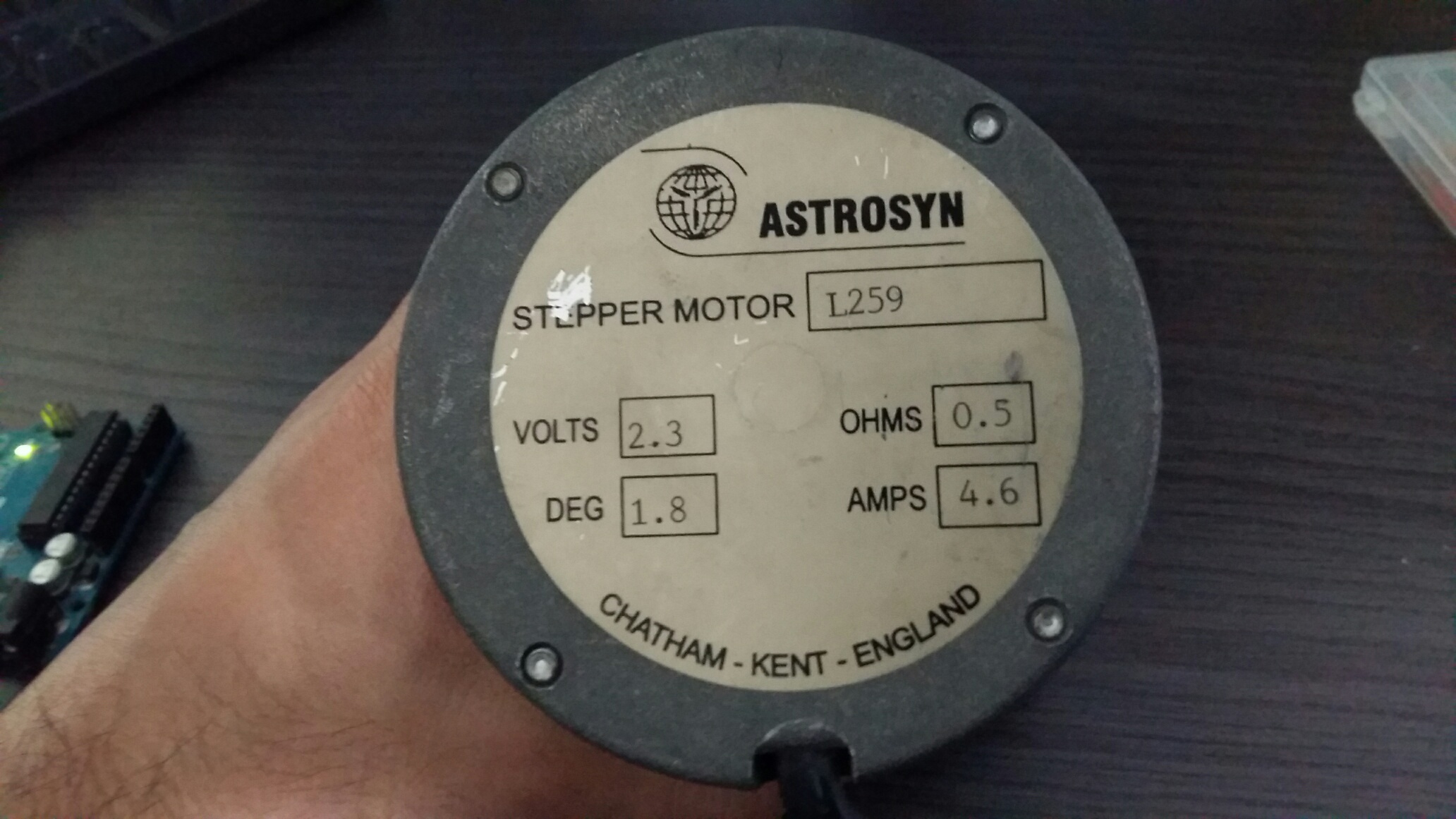
Stepper Motor Details:
Volatge: 2.3 V
Current: 5A
Phase: 4 phaes, 8 Wires
Regrads,
hi Guys,
Can i use a 12 V 5 A wall wart power supply for my motor (Photo attached)? Will there be overheating of the chip because the motor is only 2.3 V?
Stepper Motor Details:
Volatge: 2.3 V
Current: 5A
Phase: 4 phaes, 8 Wires
Regrads,
If you are supplying 12v to a shield that can accept 12v vin yes, it's fine (see the shield datasheet).
If your question is: can I apply 12V to a 2.3V motor?...well, of course you can but it will not overheat, it will simply blow up! (seriously, don't do that)
Hi Staccato,
When I have used plug in power supplies they tripped at about half of the rated current but YMMV.
If your stepper controller allow current limiting (to what ever the power supply can handle) then no problem but you will find the torque and speed will be reduced. That may not be a problem depending on your application.
I might also hint that the rating is also per phase so double that for full step - two phases at a time operation. You can run stepper motors one phase at a time but the torque and maximum speed will be reduced.
Regards Alan0
c0rsa1r:
If you are supplying 12v to a shield that can accept 12v vin yes, it's fine (see the shield datasheet).If your question is: can I apply 12V to a 2.3V motor?...well, of course you can but it will not overheat, it will simply blow up! (seriously, don't do that)
No it does not work like that.
Most steppers are rated at between 2v and 4v, but they are run at higher voltages for speed.
They get away with it by using either ballast resistors (old school) or PWM.
regards Alan0
Hi,
Thank you very much for your helpfull replies.
I am using a arduino motor shield R3 to drive the motor.
When using 12V 5A power supply the motor dosent work and the shield over heats like crazy.
but works fine when powered by 8 AA batteries.
Can you please suggest the optimum wall wart power supply?
regards,
Alan0:
No it does not work like that.
Most steppers are rated at between 2v and 4v, but they are run at higher voltages for speed.
They get away with it by using either ballast resistors (old school) or PWM.regards Alan0
Didn't know that! Thank you for the info!
Hi c0rsa1r,
No problems.
There is quite a lot of misinformation/misunderstanding on the forum.
Make for interesting reading!
I noted one guy had tied the PWM inputs on his driver board to Vcc and wondered why it blew up.
Not really his fault, the datasheet does not make it very clear how to use the device (and who want to read that).
I have spent the last two days trying to get the Sparkfun Monster Moto shield working.
I tried like hell to avoid having to use a timer and interrupts but in the end I had to read the AVR datasheet - now that is not much fun.
My motors are rated at 2.8v (and 1.7A) and the power supply is 12.5v so all that is needed is a PWM duty of about 20% and everything runs cool. The main headache is getting a reasonable high PWM frequency. The Arduino analogWrite is only 490 Hz and 980 Hz and not up to the task (very limited operational envelop and very noisy). For steppers you need at least 8 kHz (my code uses 20kHz).
In practice as the motor speeds up the duty can be increase.
Some of the later board do have current regulation (i.e. PWM) on the board and should be preferred.
Regards Alan0
staccato:
When using 12V 5A power supply the motor dosent work and the shield over heats like crazy.
but works fine when powered by 8 AA batteries.
Can you please suggest the optimum wall wart power supply?
Does not really matter. What ever you have can be made to work.
Your stepper has 4 phases (8 wires) so basically you can use 2 (leave two out) or use then in parallel or use them in series.
I don't know what the application is or whether you need all the torque that is available (I am guessing not), so wire it in series (look to google for examples - make sure you wire the same phases). In series the resistance and operation voltage will be double (but the inductance will be double too. i.e. slower - did you want to run fast?).
Actually thinking about it you will have fun trying to workout what phase is what without the datasheet!
May be better to try for two phases only (less trial and error).
Next set the Arduino to drive the stepper (you could use the stepper library or roll your own - not hard).
Next (the hardest bit) is you need to set up a PWM for the driver board (unless it already has current limiting - check the documentation). As a demo you can use pins D5 and D6 as the PWM frequency is higher (i.e. 980 Hz). I said demo as it will sound terrible and not have much of an operational envelop. Basically set the analogWrite to say 20% duty cycle (i.e. 50). it should run without overheating or pulling you power pack down.
Next use a multimeter to measure the power supply current at very low speeds and increase the PWM duty until you are happy or the power supply trips out.
Don't expect much more than 60 RPM with this set up.
Really you will need to program a PWM with a frequency of at least 8 kHz.
I built a driver program recently for the MonsterMoto shield so if you have that then you are in luck.
Regards Alan0
Dear Alan,
Thank you very much for your reply.
I can not disconnect two phases as I need high torque. I need to control the motor speed which will be carrying a load.
Could the be overheating because of some error in the code? Please advise.
Regrads,
Code </>
#include <Stepper.h>
const int stepsPerRevolution = 400; // change this to fit the number of steps per revolution
// for your motor
// initialize the stepper library on pins 8 through 11:
Stepper myStepper(stepsPerRevolution, 12, 13);
int stepCount = 0;
int buttonState = 0;
const int buttonPin = 2; // the number of the pushbutton pin
const int ledPin = 13; // the number of the LED pin
const int pwmA = 3;
const int pwmB = 11;
const int brakeA = 9;
const int brakeB = 8;
const int dirA = 12;
const int dirB = 13;
void setup() {
// nothing to do inside the setup
Serial.begin(9600);
// set the PWM and brake pins so that the direction pins // can be used to control the motor:
pinMode(ledPin, OUTPUT);
pinMode(buttonPin, INPUT);
pinMode(pwmA, OUTPUT);
pinMode(pwmB, OUTPUT);
pinMode(brakeA, OUTPUT);
pinMode(brakeB, OUTPUT);
digitalWrite(pwmA, HIGH);
digitalWrite(pwmB, HIGH);
digitalWrite(brakeA, LOW);
digitalWrite(brakeB, LOW);
}
void loop() {
buttonState = digitalRead(buttonPin);
if (buttonState == HIGH)
{
digitalWrite(ledPin, HIGH);
int sensorReading = analogRead(A0);
int motorSpeed = map(sensorReading, 0, 1023, 0, 100);
myStepper.setSpeed(motorSpeed);
myStepper.step(stepsPerRevolution);
Serial.println(motorSpeed);
}
else
{
digitalWrite(ledPin, HIGH);
int sensorReading = analogRead(A0);
int motorSpeed = map(sensorReading, 0, 1023, 0, 100);
myStepper.setSpeed(motorSpeed);
myStepper.step(-stepsPerRevolution );
Serial.println(motorSpeed);
}
}
Alan0:
No it does not work like that.
Most steppers are rated at between 2v and 4v, but they are run at higher voltages for speed.
They get away with it by using either ballast resistors (old school) or PWM.regards Alan0
By using ballast resistors (horribly inefficient) or chopper drivers
I have several questions to the OP:
What are you intending to drive with this motor?
What speed (rpm) do you want?
Why have you chosen a high performance stepper motor?
You cannot possibly drive that motor with a motor-shield, it needs a proper
commercial chopper driver capable of 5A or more.
I am modifying an old CNC machine and need to control the direction and speed of the motor. I dismanttled the motor from the machine itself.
I want as low RPM as possible.
Theres no way the motor can be operated using arduino motor shield r 3?
Can the commercial chopper driver be connected to the arduino? If so can you please suggest a driver?
regards,
Stationary is as low rpm as possible.
You need to say the maximum speed you need, that is the limiting factor.
Commercial stepper drives rated at 5A and above are available to those that look for them.
The CNC machine didn't have motor drivers?
What do you want to do with the motor - its quite possibly the wrong motor for your purposes
(it is the right motor for a high performance CNC machine).
The motor will be carrying a heavy load in a straight path in varying speed. Can the commercial stepper driver be connected to arduino?
And what power source would be required for the driver? 2.3V 5 A or 12V 5 A
Hi staccato,
Always hard to read other peoples code.
I don't see where you are controlling the current to the steppers?
Perhaps you have set in in hardware (on the driver board).
I see that you have set the PWM pins high, that means for a board with no ballast resistors (yeah, tell me about how inefficient is is!) or a "chopper" (which means PWM), you are applying the full power supply (12v?) to your motor which is rated at 2.3v. So yes everything overheats and the power supply trips out. (If you run your motor at speed you could get away with it).
You can test the setup by using analogWrite on pins 3 & 11 to the driver board PWN inputs.
The frequency is too low to be practical (i.e. 490Hz) but you can test the code and steppers if the speed is low (say 15 RPM). Use analogWrite(3,50) and/or analogWrite(11,50) instead of digitalWrite(3) and/or digitalWrite(11). It sound terrible by the way! An use a multimeter to check the powersupply current draw.
Now your are in luck, Timer2 which is generally unused and is connected to pins 3 and 11 so you just need to write some PWM code (for 20kH) to replace the analogWrite.
Regards Alan
staccato:
I want as low RPM as possible.Theres no way the motor can be operated using arduino motor shield r3?
Can the commercial chopper driver be connected to the arduino? If so can you please suggest a driver?
Hi staccato,
I am using the Sparkfun MosterMoto shield on my Uno R3.
Its rated at 30 amps per phase (YMMV - Datasheets are often overstated) so plenty of capacity for your application. The only change to your code is pin numbers and names. But you will need to use PWM to control the current.
Regards Alan
Can i piggy back the L298 P chips to gain more current?
Regards,