Ok... although I have some experience with electronics (mainly arduinos and fixing maybe a dozen power supplies) I'm not anywhere near good but I do know how to not get electrocuted from stupid mistakes... which I appear to have made. This will all be very vague because none of you know exactly what I am working on or what I may have done. I just hope for a general overview of what I might have done wrong. I decided to troubleshoot a power supply from a dead lcd tv. I really didn't need to do this but at one point I decided to look at the waveform on the big capacitor on the primary side of the supply. I turned on the power supply then my scope. I took the ground clip from the scope and connected to the negative side of the big cap and bang! There was a pop and a flash and it now a couple of components like a cap and coil near the fuse have a burn mark on them. The fuse is still good. What did I do wrong?
freakdaddy:
Ok... although I have some experience with electronics (mainly arduinos and fixing maybe a dozen power supplies) I'm not anywhere near good but I do know how to not get electrocuted from stupid mistakes... which I appear to have made. This will all be very vague because none of you know exactly what I am working on or what I may have done. I just hope for a general overview of what I might have done wrong. I decided to troubleshoot a power supply from a dead lcd tv. I really didn't need to do this but at one point I decided to look at the waveform on the big capacitor on the primary side of the supply. I turned on the power supply then my scope. I took the ground clip from the scope and connected to the negative side of the big cap and bang! There was a pop and a flash and it now a couple of components like a cap and coil near the fuse have a burn mark on them. The fuse is still good. What did I do wrong?
You did not use an isolation transformer to feed the TV PSU. Since it came from a device that was in an insulating enclosure, and BIG notices were on the enclosure that there were no user repairable components inside, the manufacturer was not required to isolate the PSU from the power line ground.
Paul
An oscilloscope has its ground connected to the mains earth. The cap in the power supply was shorted out to mains ground hence the bang. It is fairly common mistake for beginners.
There are special probes to do this sort of measurement but they are expensive.
In the old days we could remove the grounding wire from the plug but these days with moulded plugs it is not easy to do.
Got it! Thanks! Love learning!!!!
Watch this:

larryd:
Watch this:
So fitting!!!! Thanks!
freakdaddy:
I really didn't need to do this but at one point I decided to look at the waveform on the big capacitor on the primary side of the supply. I turned on the power supply then my scope. I took the ground clip from the scope and connected to the negative side of the big cap and bang! There was a pop and a flash and it now a couple of components like a cap and coil near the fuse have a burn mark on them. The fuse is still good. What did I do wrong?
The negative clip of the scope is generally electrically/physically linked (as part of the internal scope wiring/design) to 'earth'. The tv circuit has a ground that's also linked to earth. So connecting the negative clip to the negative side of the capacitor made that particular side of the capacitor become earthed and become grounded. So that terminal of the capacitor became grounded when you connected the negative clip to it.
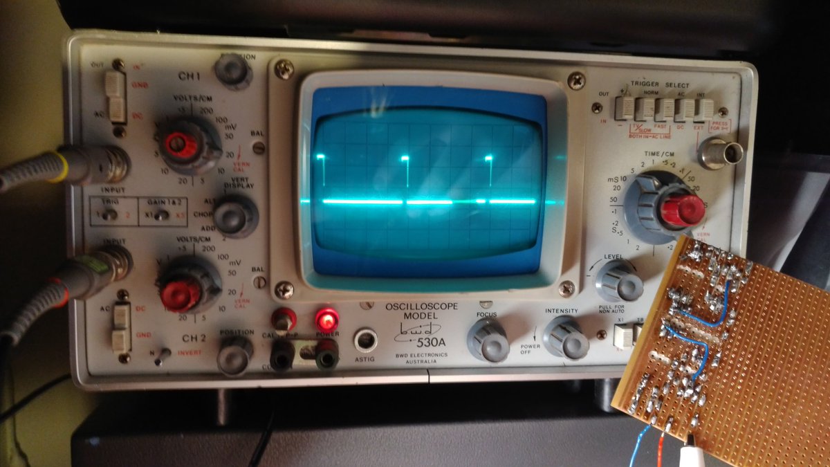
In the older days - before 'big brother' came along, some old-school analog oscilloscopes were designed with an electrical jumper link that you could remove on the front panel - that allowed the negative clip of the scope to be disconnected from earth - such as in this picture here (with the removable shiny metal link under the red light - which, when removed would have allowed you to measure what you wanted to measure - but usually recommended to put the link back in afterwards for electrical safety reasons).
The mains input to the PSU goes to a bridge rectifier, the capacitor is on the DC side of the rectifier. During negative half cycles of the mains the bridge rectifier connects live to the negative of the capacitor. Earth is connected to neutral at some point between your local electricity distribution transformer and your house. Connecting earth to the negative (or positive) of the capacitor is shorting live to earth / neutral for half of the half cycles.
If you need to do this sort of thing buy a mains isolating transformer (I use one taken from a shaver adaptor designed to be used in a bathroom).
PerryBebbington:
If you need to do this sort of thing buy a mains isolating transformer (I use one taken from a shaver adaptor designed to be used in a bathroom).
And you use a 10W transformer with a 5 minute duty cycle to power a 60+ Watt TV?
And you use a 10W transformer with a 5 minute duty cycle to power a 60+ Watt TV?
![]()
I wondered if anyone would spot that! :o
No, I don't. I don't fix TVs. I don't work on live mains very often but when I do it is generally low power, for example my UPS monitoring system has a PIC connected directly to the mains to monitor the voltage and frequency (data sent out via opto isolator). The power consumption of that bit is well below the capability of the transformer.
Just in case anyone reading this is wondering, first, if you have to ask about working on live mains then you probably shouldn't be doing it (but then I have made my own 'dramatic' mistakes (ahem....) and learned from them).
A mains isolating transformer helps. If you use one from a shaver unit as I have suggested they are only good for a few James. Bigger, beefier (and more expensive) isolating transformers are available.
As well as two isolating transformers gathering dust here - somewhere - I also have a Variac to stub my toes on. Unfortunately I am not kidding!
Paul__B:
As well as two isolating transformers gathering dust here - somewhere - I also have a Variac to stub my toes on. Unfortunately I am not kidding!
Had the same problem here last June, wife got rid of anything over 15 pounds ![]()