Hello,
I am making a device based on an ESP32 and all the sensors i need to connect are 3.3v
I was looking for a small power supply (AC / DC converter) and bought a few of these:
Multicomp Pro MP-LS05-13B03R3 ([MP-LS05-13B03R3 - Multicomp Pro - AC/DC PCB Mount Power Supply (PSU), 70 to 430VDC, ITE (farnell.com)](https://nl.farnell.com/multicomp-pro/mp-ls05-13b03r3/power-supply-ac-dc-3-3v-1a/dp/3584006?st=ac dc))
The stupid i am, i bought it and as they arrived i started to look at how to use them. To be honest, i thought i would just connect 230v to the pin 1 and 2 and get 3.3V on pin 3 and 4 or 5 and 6 (didn't know the exact difference between the 4 output pins).
Now i started to look at the datasheet (3167206.pdf (farnell.com)) and see that there is much more to connect than just the 4 wires ![]()
I think i should go for this design:
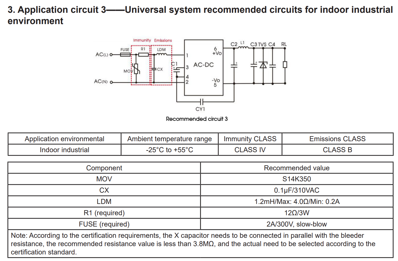
I think i understand how to add the fuse, resistor and CX capacitor, but i cannot figure out what LDM is, and what MOV is, also i am not quite sure i understand what everything is behind the outputs 3 till 6.
If anyone would help me a bit i would appreciate it really much.
Thanks a lot!