joanlluch:
Thank you very much for this. I think this might indeed work, and the idea of the mosfet is an excellent one!. I'm almost sure the D2 diode is a regular one. I think its only purpose is to protect whatever is connected to the USB (possibly a computer) from getting an undesirable voltage from the RAW pin.
Yes, I think that's right.
About your circuit, I'm unsure about the best way to pick up the UVCC. I suppose this implies messing a bit with the pro micro board. Maybe I can take it from the left side of the J1 jumper on the schema?, so I still have the 500 mA fuse operational? Or is there a better way that you can think of?
I don't have a Micro to look at, so I can't say for sure. But if you can solder a wire to VBUS1 at the USB connector, or on the high side of the fuse, I think that would be a good tie in to UVCC. You would still have the fuse for the Micro, but the fuse wouldn't limit battery charging. If you tie in after the fuse, then the combined charging current and Micro current will be limited to 500ma, realistically more like 400ma, and that may extend your charging time significantly. Of course the other option is to just remove the fuse, which would also probably give you an easy tie-in point. My Mini doesn't have such a fuse. I don't know about the other Arduinos.
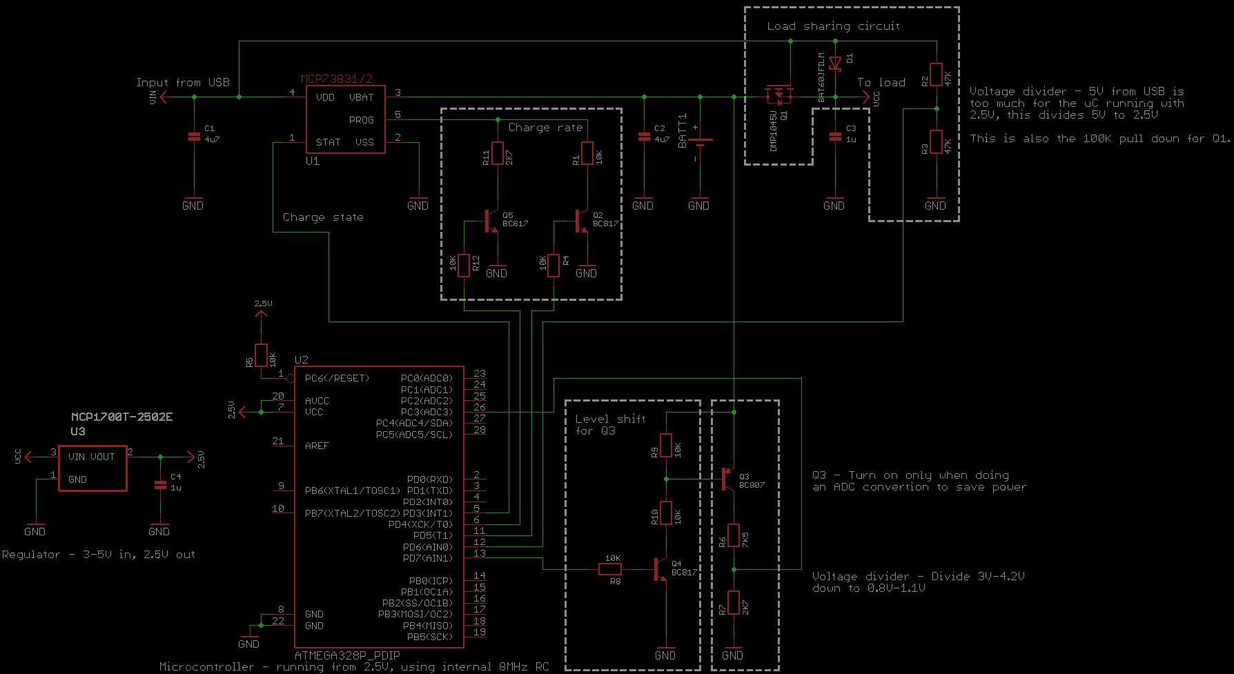
My initial thought was to use the RAW pin, not as a power input, but as source of power to charge the battery. I noted that when I plug the USB connector, I have about 4.8 V there. I suppose it is not exactly 5V because of the voltage drop in the existing D2 diode. Then I would use the VCC pin to supply power (3.3v) to the system. This requires an external voltage regulator (and the one available in the pro micro would remain unused). The mosfet circuit that you suggested for "load sharing" is still applicable in exactly the same way, except that it would have a 3.3v regulator after it and will be connected to the VCC pin.
I'm having difficulty picturing how that would work. But if you want to sketch out what you have in mind, I'll look at it. But you would still have the fuse limiting your charging current.
I have some questions:
It puzzles me that when nothing is plugged in the USB connector, and a stable 3.3V source is connected to VCC, there's 3.3V in the RAW pin. I do not understand why?. Does this imply that the voltage regulator on the board leaks tension in the opposite direction? Is this something to be expected?
That puzzles me too. Some regulators have protection diodes going from output to input, but then there would be a diode drop. I don't think the MIC5219 shown on my schematic has that. It would not be unusual to have some voltage show up on RAW, but I don't understand how it could be equal to the Vcc input voltage.
Also, in case I decide to go to my approach (just to avoid excessive messing with the pro micro board). Do you think that the existing 3.3v regulator on the pro micro board can cause some problem (because to some extent we would have two regulators working in parallel when the USB cable is connected)?
Well, you would have to prevent that situation from happening because you can't have the battery powering your external regulator while it's being charged. So both regulators can't be on at the same time. What's not clear is how you would accomplish that.
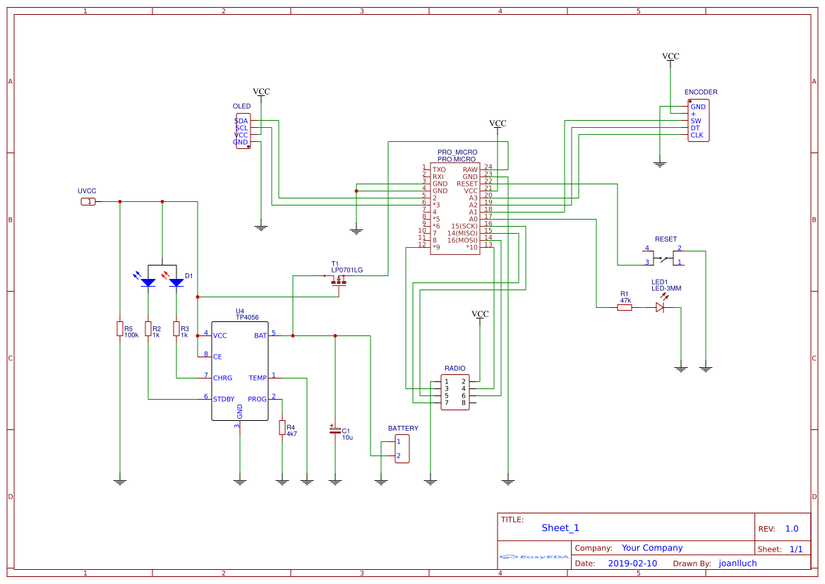
Finally, please can you suggest a suitable P-channel mosfet that would do it?. I have long experience in software development (much before arduino), but not that much on electronics or hardware components. I mean, I understand basic electronic circuitry, but it would be great if you point me to at least a family of suitable p-channel mosfets for that application. I have yet to determine the exact consumption of the project, but I 'guesstimate' that it will be no more than 100mA. The project consists on the pro-micro board, the battery charger + battery, a 1.3" oled display, and a nrf24l01 module.
The mosfet only has to handle what the battery will supply, which is everything except the charger. But for 100ma, you might look at the TP2104. It's kind of a middling mosfet, not great on any spec, but does pretty well. More expensive, and more capable, would be the LP0701. Both come in through-hole TO-92 packages as well as surface mount.
Thanks!
You're welcome.


