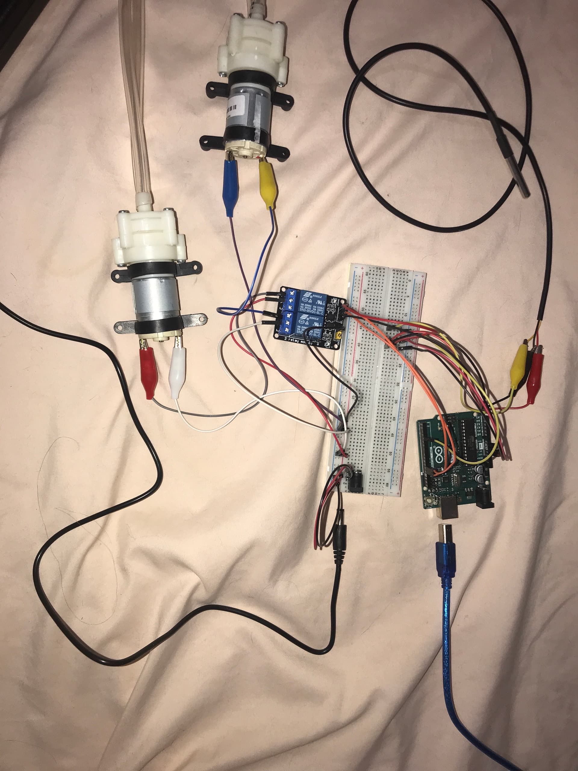
Hey guys! I'm a grade 11 student working on an Arduino project for my science fair presentation. I am trying to control 2 12V water pumps with an Arduino uno, a 2-channel relay, external power supply, and a breadboard. The Arduino is also connected to a temperature sensor. I have a problem with my relay as it keeps clicking rapidly with flashing red lights. I put my exact circuit (with one pump instead of 2 bc the problem occurs regardless) on a circuit editor, and it says I should use a MOSFET transistor in addition to the relay. I will attach a picture of my circuit, as well as my code. Can someone please explain the problem to me? my code is for a one pump system, but it was malfunctioning regardless
#include <OneWire.h>
#include <DallasTemperature.h>

// Data wire is plugged into port 4 on the Arduino
#define ONE_WIRE_BUS 4
#define PUMP_PIN 13

// Setup a oneWire instance to communicate with any OneWire devices (not just Maxim/Dallas temperature ICs)
OneWire oneWire(ONE_WIRE_BUS);

// Pass our oneWire reference to Dallas Temperature.
DallasTemperature sensors(&oneWire);

int numberOfDevices; // Number of temperature devices found
DeviceAddress tempDeviceAddress; // We'll use this variable to store a found device address

void setup(void) {
  // start serial port
  Serial.begin(9600);

  // Start up the library
  sensors.begin();

  // Grab a count of devices on the wire
  numberOfDevices = sensors.getDeviceCount();

  // locate devices on the bus
  Serial.print("Locating devices...");
  Serial.print("Found ");
  Serial.print(numberOfDevices, DEC);
  Serial.println(" devices.");

  // Loop through each device, print out address
  for(int i=0; i<numberOfDevices; i++) {
    // Search the wire for address
    if(sensors.getAddress(tempDeviceAddress, i)) {
      Serial.print("Found device ");
      Serial.print(i, DEC);
      Serial.print(" with address: ");
      printAddress(tempDeviceAddress);
      Serial.println();
    } else {
      Serial.print("Found ghost device at ");
      Serial.print(i, DEC);
      Serial.print(" but could not detect address. Check power and cabling");
    }
  }

  pinMode(PUMP_PIN, OUTPUT);
}

void loop(void) {
  sensors.requestTemperatures(); // Send the command to get temperatures

  // Loop through each device, check temperature data
  for(int i=0; i<numberOfDevices; i++) {
    // Search the wire for address
    if(sensors.getAddress(tempDeviceAddress, i)){

      // Print the data
      float tempC = sensors.getTempC(tempDeviceAddress);
      Serial.print("Temp C: ");
      Serial.print(tempC);

      // Check if the temperature is above 35 degrees Celsius
      if(tempC > 35) {
        digitalWrite(PUMP_PIN, HIGH); // Turn on water pump
        Serial.println(" - Turning on water pump");
      } else if(tempC <= 35) {
        digitalWrite(PUMP_PIN, LOW); // Turn off water pump
        Serial.println(" - Turning off water pump");
      }
    }
  }

  delay(5000);
}

// function to print a device address
void printAddress(DeviceAddress deviceAddress) {
  for (uint8_t i = 0; i < 8; i++) {
    if (deviceAddress[i] < 16) Serial.print("0");
    Serial.print(deviceAddress[i], HEX);
  }
}
This is the circuit I have created (not including the 12v power supply as it was not available in the simulator) with serial monitor readings included. The code and circuit both work in the simulation.
I'm so sorry but I'm new to electronics and Arduino so I don't exactly know how to make a schematic could it be a tinkercad diagram or does it have to be an actual circuit diagram?
The JD-VCC jumper is the important one, because it takes the relay supply ‘away from the Arduino, and lets you feed it from the separate power supply that has enough current.
If you were using a bare relay that would be true. But you are using a relay module, which already contains a MOSFET or similar circuit.
You could use a suitable MOSFET, like IRL44Z for example, in place of the relay, which would save space and extend your circuit's battery life. Relays are a very wasteful way of controlling your pumps.
Unfortunately the picture is not so useful, the wiring is a spaghetti mess, we can't follow where the connections are going. Your circuit diagram is also not so good. To small and blurry, we cannot read the pin names or component values. Schematics are way better than circuit diagrams and photos for understanding a circuit and spotting errors.
The Uno should be able to supply enough current for at least one relay because it is USB powered.
If the Uno is later powered from the 12V battery, things will be different. Powering one relay might be ok, but 2 relays will overload the Uno's regulator. Those MOSFETs could fix that.
I'm so sorry for the complete mess of a circuit that I have, but I'm gonna do my best to explain it bc idk how to make circuit schematics/diagrams as I'm completely new to electronics. I should've clarified that I (intended to) power my relay through an external power supply, but as mentioned above in this thread, I did not remove the JD-VCC jumper on my relay module. My external power supply is 12V tho, which could be a problem as I'm using a 5V relay. I'm scared to power it externally now that I realized this as I'm afraid it will short circuit or explode.
Can my relay be powered by a 12V supply, or do I need a 5V one?
That's not a schematic, it's an annotated photograph. But it shows a relay module equipped with opto-isolators. With this type of module, a LOW signal will usually switch the relay on and a HIGH will switch it off.
Lots of serial monitor output there, so let's see it. Copy a sample of the serial monitor output and paste into your post between code tags. We may be able to see if the rapid relay clicking is a code issue.
Thank you for the suggestion, I will paste the code from the serial monitor into the post. I was also unaware that the photo I posted was not a schematic, so thank you for telling me.
Your relays are 5V relays and would be damaged by 12V supply. You can get 12V relay modules. But my recommendation is replace the relays with MOSFETs. MOSFETs have several advantages. As well as being small, they are quiet, don't wear out, are much more efficient, which will extend battery life and avoid the problem of overloading the Uno's regulator.
Ok, I've had my morning coffee and am now properly awake.
Two small but very important components are missing from your circuit. You must add flyback diodes across the pump terminals, or close to them. Any 1N400x type will be suitable. Cathode to +, anode to -.
Without flyback diodes, when the pumps switch off, negative voltages will be generated which can cause the arduino to misbehave and maybe reset itself, or worse, damage the arduino. You have a common ground between the 5V and 12V circuits, so the relay is not able to isolate the Arduino from those damaging negative voltages. You could re-wire the circuit so that the 5V and 12V circuits are isolated.
I also noticed that in your wiring diagram, the relay is not connected to the pump. It's serving no useful purpose. Your circuit shows a MOSFET switching the pump. Is this what you have wired in reality? What model of MOSFET?
With a MOSFET, you have to have a common ground between 5V and 12V circuits, so those flyback diodes are vital.
Don't do that please. Only update old posts to correct spelling or other mistakes, broken links etc. Any new information should be added in a new post. Updating old posts can make the replies from others sound crazy by pointing out errors which are no longer there or requesting information which is already included (but wasn't at the time).
You didn't make that clear at all. So that diagram was not only unreadable, it was also misleading and inaccurate.
In electronics, as with many engineering & science subjects, detail and accuracy is so important. We are trying to help you, but we can only see what you post, not what's actually in front of you. Please think carefully about what you post: is it complete, accurate, is it confusing?
Should I then remove that diagram from the post, or should I make an edit stating that it was a diagram found on a circuit maker website? I did actually write that an editor website suggested a MOSFET in my original post:
No, don't bother now. Just bear these points in mind in future.
Where is the serial monitor output you were going to post? I can see a tiny part on the Wokwi image, but not the messages printed in setup(), and what we need to see is the actual output from the real Uno.