Powering an arduino RC car

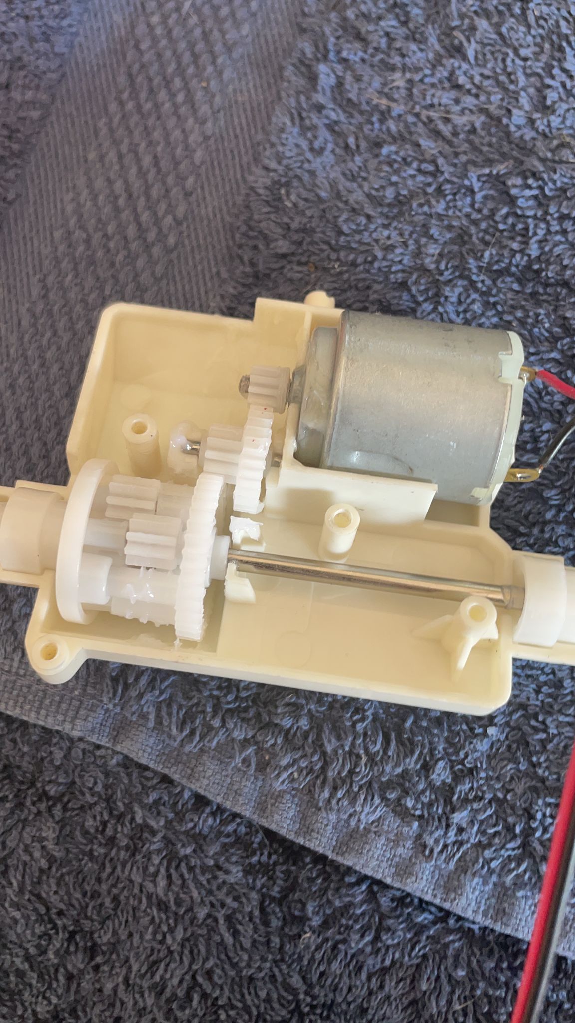
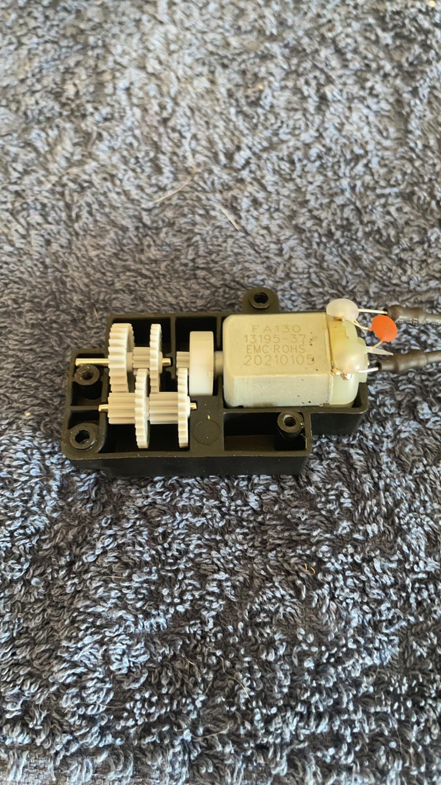
Hi everyone! I'm a first year automotive stundent and for out final project we are building an RC car using arduino. Being a real fanatic and enthusiast, I took it to the next level by purchasing a Lamborghini RC for it's motor and body. The RC ran on 5 1,5V AA batteries in series and was about 10kph fast (manufacturer claim).

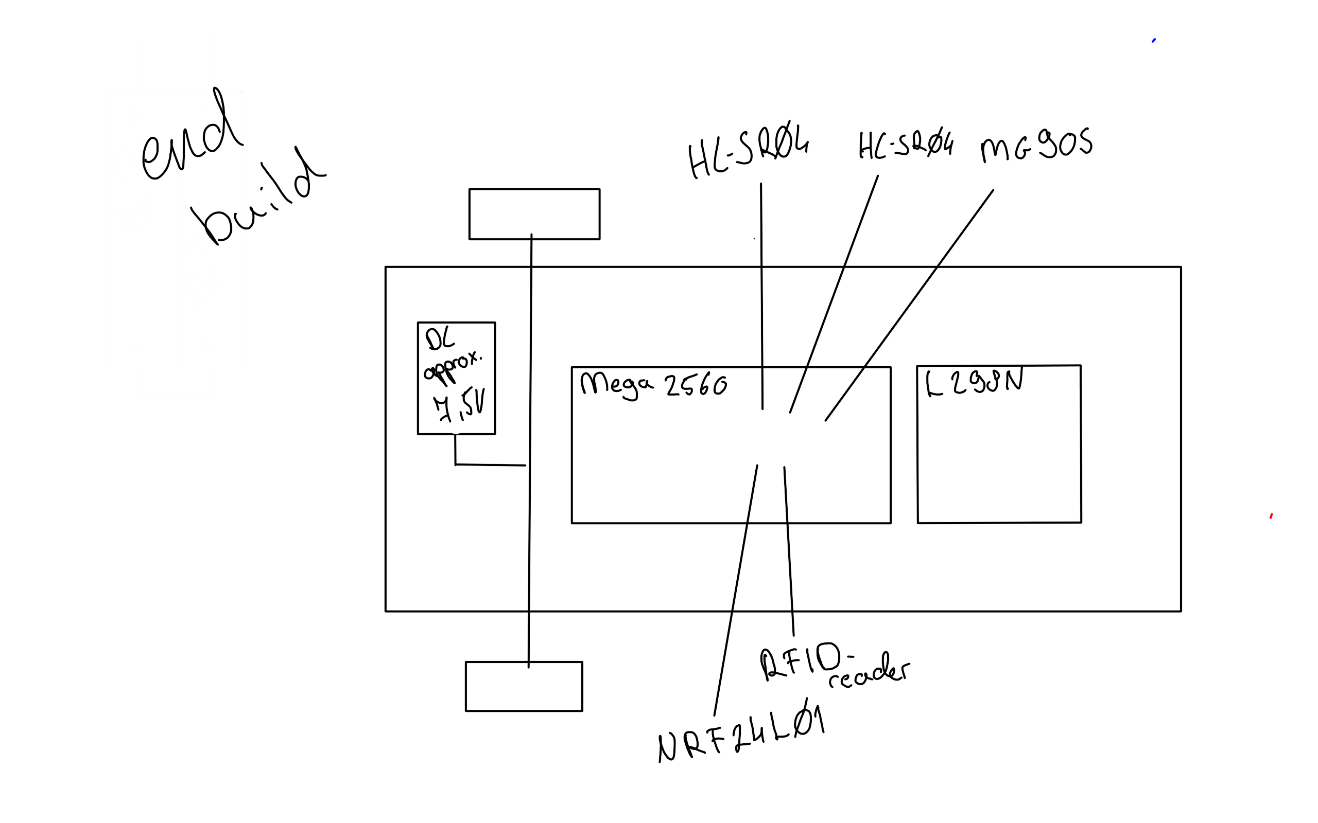
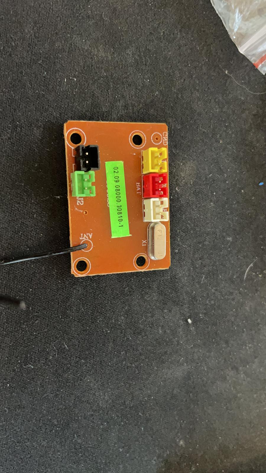
For my own build I'm using the factory DC motor with a L298N h-bridge, a Mega2650,a joystick, 1 sonar sensor, an nrf24l01 transmitter and a sg90s servomotor. I will be adding an RFID reader, 1 extra sonar and I will be replacing the sg90s with the mg90s plus the Mega with a NANO V3 for packaging purposes. While working on my desk, the arduino connected to the pc and the supposed 7,5V (the 5 AA in series) cell pack connected to the Hridge which then of course connects to the arduino via Vin, everything was fine. Wheels were spinning, servo was working and all was well.

(Quick question in between. The VCC and GND from the L298N MUST connect into the arduino vin and gnd right? when I used separate batteries for the board and bridge, without connecting vcc to vin, my motor was dead. Is that normal?)

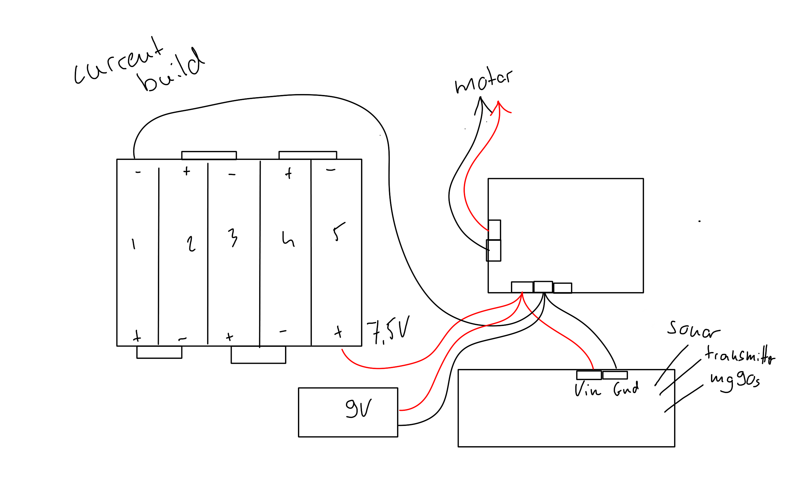
When I disconnect the arduino from my PC and just leave it with the supposed 7,5V into VCC into Vin and GND, and put the car on the ground to actually toy around with it, life gets a bit harder. Its like the car can't carry its own weight. It can (somewhat) go forward and backward, but there is no possibility of me using the joystick to turn via the servo and still go forward. When i try to do that, it just 'freezes'. Plus, everything is extremely slow, even though the motor is set to spin at int 255 at full joystick extension. In the air however, the wheels spin at their respective speed and I can use all controls at the same time. After this fiasco I connected a 9V battery into VCC of the ln298n and gnd. So now it was the supposed 7,5V and 9V in VCC together, both grounded of course (current build sketch). Again, the car wasn't able to pull it's weight, it was a bit better though. In the air, all was well. Actually, that's not true, even in the air it used to 'freeze' without the arduino connected to my PC.

Since it's 3AM right now, I will be going to the store and buy all new 9V and 1,5V batteries in the morning. They could just be 'empty' from the tens of hours of coding and testing. I will also get my multimeter back from my girlfriend to be able to monitor whether I'm actually at the Voltage I think I should be at or not.

The DC motor also has a quite annoying whine to it. I don't know why that is, but when the motor is turned off, dig.write.LOW for both, its silent. Turning the joystick also increases this whine. When connected to a 9V battery directly though, nothing, silent as ever.

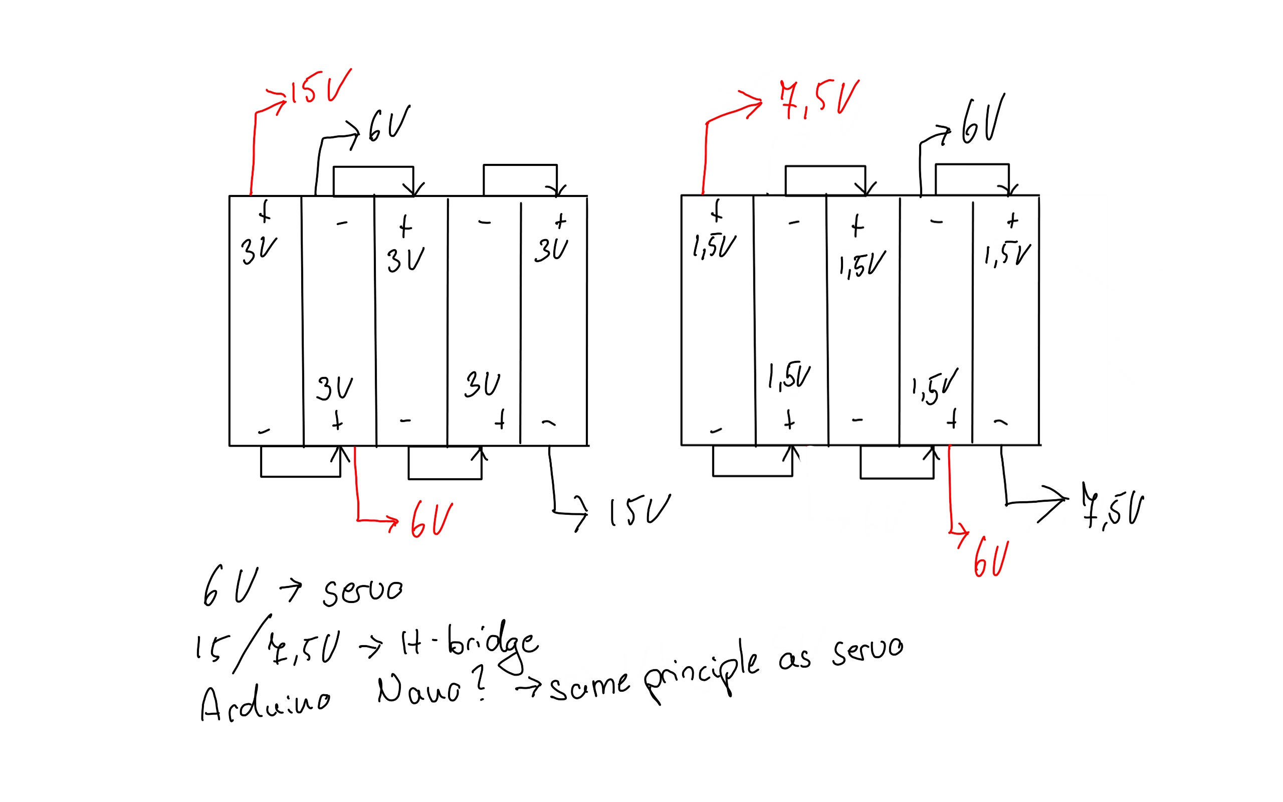
With all this given information, could you please recommend me a good power setup? I'm not exactly sure how I should wire the power cables and with what (size) batteries to get the max out of my motor and not blow up my board. I read that the n298 can handle up to 30-ish Volts and the Mega up to 12 safely. I'n not sure whether more volts on the motor directly translate into more speed, but if it does it'd be fun to be faster. It would also result in a better grade :smiley: . Thanks in advance everybody!

Here are some basic schematics.


The grounds of the Arduino and the driver board will need to be connected. There are 3 options for the +ve rails: Power the Arduino from the board's 5V output, power the board from the Arduino (but then you are limited to 5V and very limited by the current limitations of the Arduino, or power the board with your 7.5V and the Arduino with its own supply.
Even these little DC motors can draw a lot of current at stall.

A 9V battery has very little energy stored in it and very low current supply capability due to high internal resistance. It will get exhausted in short order. The 1.5V alkaline cells are better and they are used in toys all the time. Best would be a LiPo pack 7.2V nominal, which many RC car places will have. Alternatively, NiMh cells are close in voltage but do fit standard cell holders if that is important.
A good reliable power supply is important. One reason is that you may drop voltage so much that the Arduino does a brown out or glitches. Another is that these simple DC motors do produce interference and that may affect your radio.

UPDATE!

Like I said, I did purchase new cells and got my multimeter back. Furthermore i did some re-wiring.

  1. I read on the forum that connecting servo's to the arduino is kind of a no-no. Until 15min ago I too had my servo connected to my arduino, welp. So, i re-wired the Servo VCC into the Hbridge VCC and grounded it on the Hbridge. Aware of the fact that this could impact the performance of the motor, I took some measurements.
  • The Hbridge VCC GND gets 7,4V with 5 brand new Varta AA 1,5V alkaline batteries. However, the output VCC and GND for the motor is only at about 5,4V. At the motor itself, there is about 5,3-4Volts. Whenever the servo is turning, that drops to about 3,8-4,2V. My takeaway is that the servo needs a separate power supply, or the cell pack needs to be bigger so there is enough juice for the motor and the servo. Is it reasonable to use some sort of 3V AA cell x5 to get about 15V? That ought to be enough. BUT, this doesn't explain why the motor is only getting about 5,4V when there is about 7,5V going in, even without the servo connected to the Hbridge. Is that normal, or could this be a broken Hbridge?
  1. I am powering my Arduino now through 2, 3.2V cells in series, totaling up to of course about 6,4V. These are some chunky boys, 'IFR 18650 LiFePo4 1400mAh 3.2V Lithium Iron Phosphate'. These are connected through Vin and Gnd. After soldering them in series in the cell holder, I measured the voltage and all is well at 6,4V, I didn't butcher it. That should be enough for the sonar and nrf transmitter. (at first the servo was still wired to the Hbridge, more on that later!)

Thanks to the very kind user @cncnotes, i could now actually power my arduino and my board seperately.


So, after all this work I powered everything up and took it for a spin. In the air, again, everything is working PERFECTLY. I could use the servo and drive the motor at the same time, knowing that voltage drops to about 4V at the motor when the servo is working. I really had zero issues in the air. The moment the car had to pull its own weight is when things yet again got complicated. For some reason, there were moments 5-10 seconds, when I had drive and servo at the same time. Those smaller windows felt like heaven. After that it started to 'freeze' up again. When I was only trying to drive forwards and backwards, it was kind of working. Slow, but it got the job done.

It was at this point that I remembered the voltage drops when the servo is turning. To me it made sense that the voltage drops could be the reason of all my suffering. So i hooked up my powerbank to my arduino, which is rated at 2.1A and 5V. I then hooked up the 6,4V cell to the servo to give it its very own power supply. Unfortunately, the servo wasn't working for some reason. WHYYYY though. 6,4V HAS to be enough for it, right? The arduino had power, because I could drive the wheels using the joystick (again, this is being done in the air for testing purposes). So it was clearly receiving data and putting it to work. I then connected both the 6,4V cell to the Hridge VCC and grounded it on my arduino. This resulted in absolutely nothing and I still just had 6,4V and not 7,5+6,4, which I was hoping for.

My closing thoughts

  1. I have absolutely 0 idea why the servo wasnt working on the 6,4V cell. It was still attached to the right pin on the arduino and the code hasn't changed.
  2. I can't have 2 or more separate power supplies in the car for multiple things, just 1 big juicy one. As soon as I put the body on, that cell holder with place for 5 AA cells becomes my only accessible and swappable power unit. I am hoping i could use some 3-5V AA cells to power absolutely everything. Arduino's can handle up to 20V I read, so 4V AA cells at max, IF that it possible. My only realistic option other than that is putting a powerbank in the body just for the arduino which I could acces via a drilled hole to charge it. But even then, that powerbank would have to stay connected to the arduino for forever. And the servo would still need a power supply.
  3. I don't think it's an interference issue caused by the motor, that would occur in the air too after all.
  4. Could it be a too weak signal between the NRF's? I thought those are pretty juicy when it comes to coverable distance. When testing, the 2 modules never got more than 4 meters apart. When working in the air, the modules were closer to each other. However, when I'm standing next to the RC and try to drive it on the ground, like I said, life gets complicated. So again, I don't think that is the issue, but wondering whether that's possible.

Here are some pictures for reference, but I think I explained it all pretty accurately. The Mega2650 will be swapped for a NANO v3 because its way too big to make it fit with the body on.

Thanks in advance everybody!


The L298 H bridge is the problem. Up to 4V is internally lost in that ancient, inefficient dinosaur of a motor driver.

For a much better experience, try a modern, energy efficient motor driver from Pololu.

Nice work with the troubleshooting! It is amazing how far one can get even with a simple DMM.
As jremington wrote, I too think your driver is causing too much of a voltage drop.

A couple of notes:

  1. It would be great to power everything from one source.
  2. I don't think there are cheap or easily available cells that provide higher voltage or power density in AA form factor. LiIon cells are larger (like the venerable 18650 at 3.7V, which is 18 mm x 65 mm).
  3. Your choice of the LiFePO4 cells is very good. But you will need 3 in a series to get nominal 8.6V. That may or may not be enough for the motor driver circuit.
  4. This will complicate the picture with your servos: most hobby grade servos are either 5V or 6V.

Are you saying that the voltage at driver input is 7.4V, at the driver output it is 5.4V, but at the motor itself you read only 5.3 V to 4.0V?
The difference between the driver output and motor terminals should be a tiny amount, since there is only a short length of copper wire connecting the two. If this is indeed what you are saying, then there may be a problem with the connections.

As to why the servo is not working: is the servo GND connected to the Arduino GND?

Finally, in picture #2, what is the white wire and the clearish blob on it?

Thanks for the response @cncnotes!

  1. Could 5 3V 2Amp cells power absolutely everything? 'Everything' is listed in my first post and in 'final build' scematic. I found these on the internet: https://www.distrelec.nl/nl/primary-battery-lithium-aa-3v-varta-microbattery-cr-aa/p/16901543
    They are quite expensive, but if it solves all my problems and gives me a better result, which then leads to a better grade, 50 euros compared to hundreds of euros for study material and thousands for tuition, it's really nothing.

  2. Like I mentioned, as long as its reasonable, price isn't a problem.

  3. I solely used the LiFePO cells to power the arduino, not the motor circuit. Except when I tried to power the driver board with both, but that didn't work out either haha.

  4. But if it's 4-6V rated, why wasn't it running on 6,4-6,6V? Seems weird. (might have been because i fried it :cry: , more on that later.)

Yes, the driver output was at least 2V smaller than it's input. At the motor it was just around 0.1V smaller than the output, which I think is reasonable. Except when i tried to power both the servo and motor with the board, powered by the 5x 1,5V cells, the voltage dropped even more, to between 3,8-4,2V. Maybe it was a bit confusing, but when i said:

At the motor itself, there is about 5,3-4Volts.

I meant: 5,3-5,4 Volts. This may clear things up.

For the servo, when I tried to power it by itself I did:

  • Connect positive to positive servo and cell negative into negative servo. -> didn't work, could this have damaged it even?
  • I tried grounding the servo on the arduino, cell positive to positive servo and ground the cell on the arduino. However, that didnt work either.

I will be perfectly honest, between steps 1 and 2 I might have fried the servo. I accidentally connected pos cell to negative servo and vice versa. Needless to say, wires got extremely hot and I could just barely pull them out. Noobie mistake, I know, happens I guess when you are on autopilot trying to figure stuff out. After step 2 I hooked the servo up to the Hbridge and arduino, like before - when it was working, nothing. It occasionally twitches, makes annoying whines but that's about it. 0 control at all, with the same code as before. Luckily the mg90s is coming in on monday.

Finally, the white wire is the positive terminal wire from the LiFePO cells and its just running next to dried hot glue. The two share nothing and just tuched there by coincidence. That hot glue was factory and i think it was applied to preserve the solding on the on-off switch's negative terminal wire. But like I said, it was factory, I didn't do that.

Closing thoughts:

  1. I hope the listed 3V cells are doable for the build, or cheaper likely alternatives. Maybe even https://www.amazon.nl/EEMB-lithium-batterij-batterijen-oplaadbaar/dp/B07TXNSHT7/ref=sr_1_6?crid=E5PWYGERC352&keywords=3v+aa-batterij&qid=1653255760&sprefix=3v+aa%2Caps%2C62&sr=8-6
  2. I will need a new Hbridge and fast. What models am i looking at that are widely available and delivered within 1-3 working days? I personally thought that the model Im using is the most common one, could be a monday morning batch...
  3. I will try not to fry the new servo and do -> cell pos to vcc, cell gnd into arduino and servo gnd into arduino.

Thanks in advance!

:scream:
As to this question:

The L298 is common, cheap and widely available. Not very efficient, and with a 1.5 -2V drop. There is are the TB6612 based modules too, more efficient but I believe the voltage rating is lower. But you may not need a new one; see below.

The 3V lithium cells will work, but please remember that they are not rechargeable and you will only have a total of 2Ah available from them. Expensive, but as you said, worth it. Perhaps experiment with other cells and then use the expensive ones when you close up the car/finalise the project.

As to the voltage, I'm afraid the 15V will be too much for the Arduino. You'll need to double check, but I think the max is 12V. The difference between the incoming voltage and 5V multiplied by the current will be dissipated as heat.

I suspect 3 x 3V lithium cells will work well enough for you. The car's motor was designed for 7.5V, right? If there is some voltage loss in the controller, the car may just move a little slower than expected. It is easy to forget that the internal resistance of the power source really matters in case of batteries. You may not be familiar with this, but in the old days, we used to put these types of lithium cells in film cameras for rapid charging of the flash.

  1. Arduino: 9V input should be tolerable, esp if you are not drawing much current from it to power other devices

  2. Motor controller: may need to experiment. 9V may work, esp given that the lithium cells can sustain a much higher current. But it may need 12V, which probably OK for the Arduino

  3. The servos: this is going to be the most difficult part. Typically in the RC hobby field, we run servos from 4.8 to 5V. Some servos are rated at 6V. So, this is totally not the correct way to do it, but if you are desperate, you could tap off the positive lead going to the servos from the second cell. Each cell adds 3V, and tapping off at cell 2 will give 6V, if your servos can take it. (If anyone asks, you don't know nobody called cncnotes!) It might just work out for a short period of time.
    Alternatively, if you could put all 5 cells in, you would have to modify the battery holder a little bit: cut the electrical connection between cells no 2 and 3. You could then use 3 cells for main power and 2 cell for servos.

Looking at the 2 battery listings, I would choose the 3V Vartas. I don't know enough about the type listed on Amazon.
Keep going!

I drew some scematics for the 'tapping' desperado. Is this rougly what you mean? BTW, I don't know whether I would need 2 grounds or just 1 for the cell pack. I don't actually know whether I even drew it right, it could be completely wrong.

Would it then be possible to tap the 7,5V cell pack at 6V to power the servo? I guess i will just try it and measure the input on the Hbridge, see if it really affects stuff. It's theoretically the same principle after all.

Also, the cutting of the wires between cells 2 and 3 sounds rather intriguing. Is it also possible to purchase rechargeable 3V cells? Do these even exist, in AA form? It would be a huge waste to use them for testing, run them empty and spend 50 euros all over again for demonstration day.

Maybe I should ask it like this: How do people that build that build RC's make sure they have sufficient power for the motor and servo with just 1 cell pack, thats always 5 AA cells? The factory 'servo' and motor were both running on just 1 simple small board!
Pictures:
The board where EVERYTHING was connected.


The motor which I'm currently still using, because I have 0 interest in designing an own 'gearbox'.

And finally the 'Servo' they were using.

Lastly, I can't really power the arduino this way can I? Or could I power the arduino with the same 'tap' as the servo? For testing I'm just gonna power it with my powerbank or the 6,4V cell pack, but I do need a reliable final solution.

I now wired this guy up using the 6,4V cell pack, grounded on the arduino together with the servo and powering it on it's own. Who would've thought, if you dont set things on fire they work :hushed: . The SG90S is FRIED. I confirmed it by wiring up a different servo to use, and that one works just fine. I can't test this one on the ground unfortunately and drive it around because it too big and chunky to actually make fit on the chassis. But yea, RIP SG90S, you will NOT be missed!

An additional measurement, I measured the voltage at the Hbridge input, stationary 7,5V but when the motor engages, it drops to about 6,5-6,8V and if I really abuse it and switch between forward and backward really fast, it goes as low as 5,7-5,8V.

Couldn't I theoretically just get rid of the Hbridge? I wouldnt have PWM control but I'm fine with either 100% power or no power.

Cheerio!

RC cars are usually powered with a 2-cell LiPo pack, which gives nominal 7.2V.
In the old days, it was 5 or 6 NiMH cells 6-7.2V.
The speed controller would be designed to handle whatever pack voltage was being used, and many have a BEC (battery eliminator circuit), which is basically a voltage regulator. This would supply 5V to the receiver. If there was no BEC, then a separate pack was needed for the receiver. One would never do the tap trick, because of risk of failure causing a crash esp in planes.
The servos would be plugged in to the receiver, which would the supply power to the servos.
Different from your setup, but the principles are the same. Each component gets the voltage it needs.

I have created a diagram of the cells in a pdf so you can zoom into it, etc:
The 6V tap could power the servos. The 9V tap could power the H-bridge.
Cells diagram.pdf (62.1 KB)
If you use 1.5V cells, same principles will apply. Just tap between cell 4 and 5 to get 6V.
If you are providing the Arduino an unregulated power through Vin, you will need to give a 2V or so overhead for the voltage regulator to work with. So, powering it from 7.5V to 12V is doable.

You would still need a way to switch the power on and off to the motor.

The motor looks pretty small and I bet it would work from 5V to 7.5V. Much more may fry it.

Let me know how it goes. Here's hoping for much zoom-zoom without letting the magic blue smoke out.

I am happy to say that I have made major major progress today.

  1. So, first and foremost i gave a new servo, which isn't the MG90S but a RS610WP which we received from the staff, it's very own 6,4V power supply. Grounded the cell pack and the servo on the Arduino and gave it some juice! This alone made a difference.

  2. I changed my code a little bit. I realised that my backwards driving code was if valueJoy < 520 -> go backwards. BUT the middle position of the joystick is of course 512. So this was constantly messing with the arduino's little brain. This made a significant difference.

  3. I re-soldered the 10Mu capacitors between the + and - wires of the nrf24l01 transmitters. I suspected something might be off with the signals. I did all this because the negative wire of the transmitter broke off at the solder at one point during testing. It was low effort so I just did the positive wire too and the receiver aswell. Couldnt really tell the difference this made, but it reassured me.

  4. I also stopped testing it upstairs. This might sound weird, but we have a ton of wireless stuff upstairs. All the PC peripherals, a modem approximately 1m from where I was testing and Google Home stuff for both rooms. So, in my mind it made sense to go somewhere with a lot less signal activity. This seemed to help too! Now I don't actually know whether other wireless and bluetooth things can cause troubles in these transmitters, but to me it seemed like it did.

At the end the car behaved much better and was pulling it's own weight! That compared to 1-2 days ago is like a night and day difference. I was able to steer and have drive at the same time, which seemed impossible just 24hrs ago. The self stopping mechanism using sonar also worked great, although you have to be creeping to an object in order for it to work. If i just zoom at the wall pedal to the metal it first crashes, than it backs me up :smiley: .

All in all I have made major progress and I'm happy with it for today. I will have a chitchat with my electro teacher tomorrow to figure further stuff out. The motor is still whining like a baby and the fact that my motor only gets about 4-5V when there is 7,5V going has to be adressed. I want speed and I want it now! :smiley: For now im very thankful for your input @cncnotes and I will definetely keep posting updates, hopefully only good ones! :smiley:

For now I will be making sure the MG90S is in place tomorrow and I'm going to try not to fry this one :smiley: . I will also be swapping the mega for a nano and add the second sonar sensor for the back of the car. Hopefully I can tidy up the cables and get it all working withing a couple of days.

Let me know what you think about the interference of other peripherals, I am quite interested in that. I might be better off with using one of those antenna modules instead of this one.

Cheerio!

So nice to hear the good news. When one tackles a project like this, there are so many unexpected gotchas.
The interference point is a good one. Mainly because we don't know how well the NRF board was manufactured.
Having the capacitors across the motor is a highly recommended practice. I noticed that on the pics, so didn't say anything more. Glad you checked/re-did the solder joints.

Keep testing and improving. And good luck on your final presentation. :grin:

Updateeeees :slight_smile:

Today I officially fixed all my problems. Surprisingly, the problems weren't what I thought they'd be.

Short version: - YouTube

  • So, the biggest evil was the HC-SR04 sensor. I truly believe that this caused 90% of my problems. This little dude works kind of weird. This is why everything worked in the air on my desk: the sensor was getting a reading of a distance, a valid reading from 0 to about 80 (size of my desk and stuff around me). When I used to put it on the ground, the sensor went haywire. This is because it wasn't 'seeing' anything. There wasn't anything close enough that would bounce the sound waves back. When this sensor isn't getting a valid reading it returns the value 0,00. This just messes up the entire code and stops everything. I tested my theory by first, printing the reading value plus monitoring it and second, making sure the sensor could see and not see anything when I wanted so. So I made it look at a wall from about 50cm and then point it to the ceiling. That was far enough for it to return 0.00. This way I was able to confirm my suspicion and fix the code. Simply adding distance > 1 && distance != 0. BTW I am using this code to make an emergency stop, that's why I need to measure distance in front of the car. I also found that 'locking' the motor in a state in which it wants to but cannot spin works 'best' for an actual breaking mechanism.
   if (distance < 30 && distance > 2 && distance != 0){
      digitalWrite(in1, LOW);
      digitalWrite(in2, HIGH);
      analogWrite(enA, 60);
        while (distance < 30){
        distance = get_distance();
        Serial.print("distance: ");
        Serial.println(distance);
        digitalWrite(in1, LOW);
        digitalWrite(in2, HIGH);
        analogWrite(enA,255);
        }
   }
  • I tapped off the servo at 6V and powered the Arduino through the motor driver. My new TB6612 driver arrived today and I will be replacing this fossil technology very soon. The idea works great though! No complaints from me! I mean the cells will run out quicker but who cares about that :smiley: . I am now running on just 1 power supply and everything works perfectly.

Next up is replacing the Mega with a Nano and finetuning everything. But, at least it all works and I can sleep peacefully :smiley: .

Thanks again!

Fantastic :+1:
Very nice bit of troubleshooting. And just goes to show that no matter what, input validation is very important.
And cool video too.

This topic was automatically closed 180 days after the last reply. New replies are no longer allowed.