First thing first, i'm a newbie when it comes to electronics. I have 0 background and have been only doing some basic stuff.
Now, I would like to build a sunrise alarm clock using 4x1W leds (3.6V 300mA each) controlled by an arduino nano. I've done some research and came up with the following diagram. Before actually ordering the parts and building it, I'd appreciate if someone could check my circuit ?
The MOSFET would be an IRF520N. I'm using a 4ohms 2W resistor before each of the LED. Most of similar circuits I saw didn't use a resistor before their LEDS, but I believe that it had to do with the fact that they were using 12v led strips with 12v power, so they probably didn't need one. Am I correct ?
About the 10k resistor, I've read here that "it will help to switch off the MOSFET completely when the I/O goes to a low state.". I won't argue with that, so I added one. But I have to acknowledge don't I really understand why. So if someone could explain it to me, that would be awesome =)
Missing from the diagram is an RTC module.
Thanks a lot !
(I couldn't upload my diagram directly on the forum so I uploaded it here)
Wrong choice. You need a logic level MOSFET, such as the IRL540.
LEDs are current driven devices, and the current must be limited to safe values, either by choice of appropriate resistor, or using a constant current power supply. The Arduino 5V output cannot be used.
I'm using a 4ohms 2W resistor before each of the LED.
Please describe the LED power supply and your reasoning. 4 Ohms is almost certainly too low.
About the 10k resistor
It is generally required to prevent the gate from floating when the port pin is not set as OUTPUT. It should be connected from the port pin to GND, not from the MOSFET gate to GND.
You can drag a .jpg file (or other common image format) directly into the post. Most members don't like to go off site to find your information.
If your LEDs are really 3.6V, then 4 ohms would be about right for 300mA. Or I guess 5 ohms would be closer, or 4.7 if they make one like that. But I don't think they need to be 2W. Half-watt should be enough (1.4 X .3).
But the 5V supply should be connected to the 5V pin of the Nano, not Vin. And you need a ground connection for the Nano.
Am I using the 5V output ? The LED power supply should be an external 5V2A power supply.
My reasoning is just that my LED have a 3.6v forward voltage and I'm supplying 5V at 300mA. So (5-3.6)/0.3 = 4.667. I rounded it to 4ohms. Is that the issue ? Or am I missing something ? =)
It should be connected from the port pin to GND, not from the MOSFET gate to GND.
Round up instead. 4 Ohms leads to 350 mA, which is out of spec, according to your statement.
However, the linked product page does not seem to specify the maximum current. 1 W at 3.6V = 278 mA, maximum. Good design principles require staying below that value. A 5.6 Ohm resistor would lead to 250 mA, which is a reasonable choice.
You right. I'ill try not to make that mistake again.
linked product page does not seem to specify the maximum current
A comment on that store page also mentioned 3.3v at 330mA. I've found similar LED on other website and overall the specs were the one I gave initially. Although I will follow you advice and go for 5.6 ohms.
A resistor can work but high-power LEDs (1W or more) normally use a switch-mode constant-current driver (or technically a controlled-current driver if you want dimming). It doesn't waste (much) energy or heat.
With a resistor, the resistor wastes about the same amount of energy as the LED and if the resistor is near the LED it contributes to heating, when you don't want the LED to overheat. Also, high power LEDs normally need a heatsink. (1)
If all of the LEDs are controlled together, you can use a higher voltage and wire them in series to share the current (instead of the sharing the voltage) and a (higher voltage) 300mA constant-current power supply/driver can power them all.
With "regular little LEDs" you aren't using much energy (per led) and it's not worth the extra circuitry.
LED strips have a resistor (or current limiting) built-in. Non-addressable LED strips use resistors. 12V strips have the LEDs grouped in 3's sharing a resistor. And although an LED strip can use lots of energy, the LEDs are spread-out so all of the heat isn't in one place.
With addressable LED strips, there is a driver chip for each LED (or each group of 3 LED in a 12V strip) and the driver also provides current limiting. (It's not a switch-mode driver and it wastes just as much energy as a resistor.) Since the drivers are built-into the strip, you don't need a MOSFET.
(1) LEDs don't run as hot as an incandescent bulb but the LED can't handle the intense heat that a tungsten filament can.
you can use a higher voltage and wire them in series
I thought about it too, but I am kind of space restricted and having a higher voltage would also mean having to add a stepdown for the Arduino.
Just to be sure that I followed you correctly, wiring the LED in serie would allow me in this case to use less resistor and thus output less heat ?
high-power LEDs (1W or more) normally use a switch-mode constant-current driver
I didn't know that. Thank you !
But here again, space may be the limiting factor. And if heat is the only issue with using resistors, then I think I'll accept it (and the extra power consumption). The lamp should be lit up for 15 minutes a day maximum.
I was also thinking of using some aluminum base plate heatsink for the LEDs. And if necessary, the base of the lamp could be made out of metal to dump the extra heat. I'll have to see how much heat is actually generated.
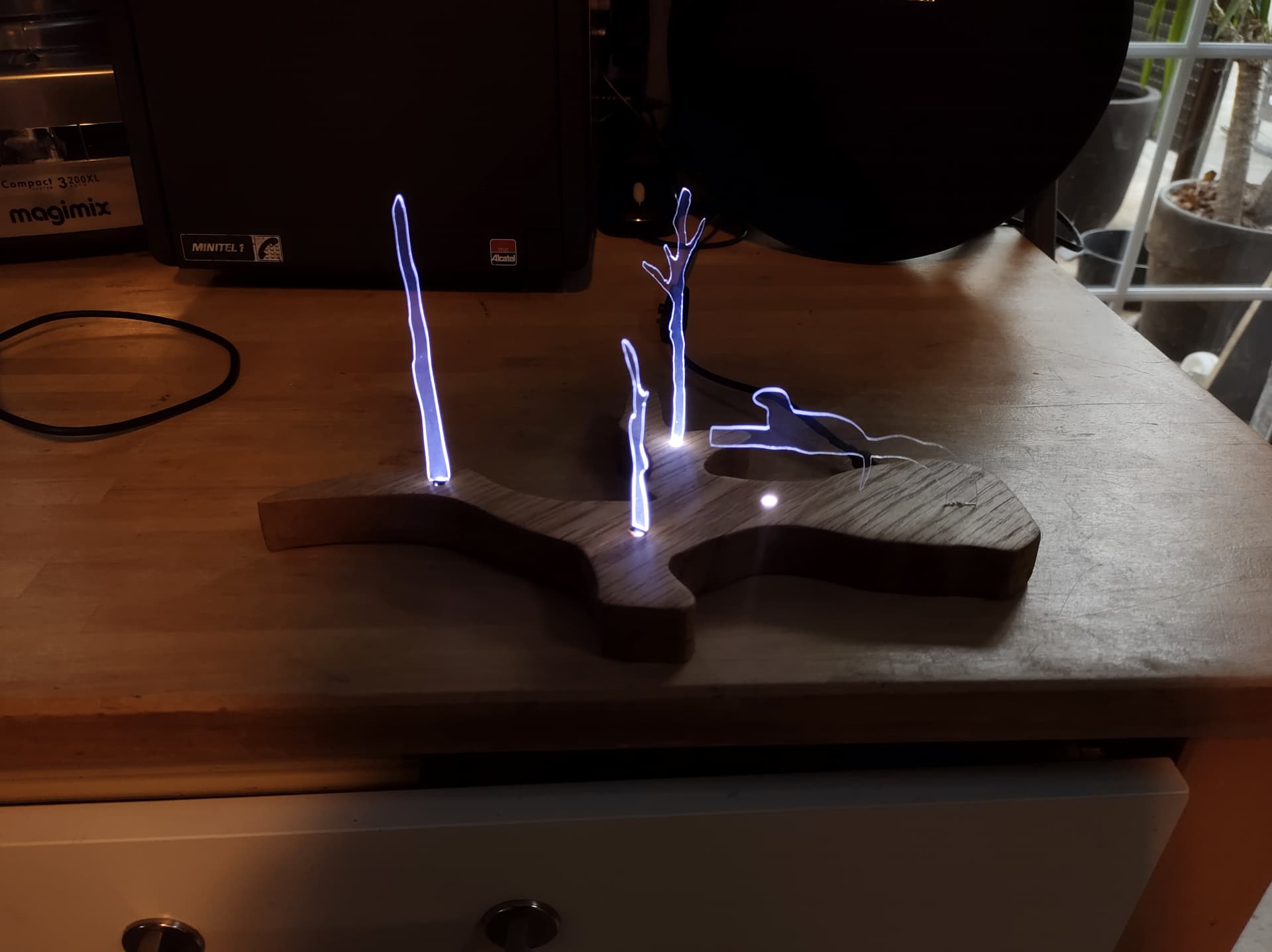
Soldering to the tabs went well ! And the small heatsinks that I bought did a wonderfull job in keeping the leds' temps in check.
I've also added a switch the to circuit in order to turn the leds on outside of the programmable hour. I set them to an extremely reduced power level to avoid overheating in case they were powered for an extended period of time.
The final product is a gift for a friend working in biology conservation on Giant otters. Hence the aesthetics. The wood piece is supposed to be shaped after part of the lake she is working at. Here are a couple of pictures if anyone is interested.


