Hi, I've been using this schematic for a number of years now, but have an application where I need another digital pin. I am powering off an LCD with a digital pin, and also a RTC chip. The RTC only uses 700uA, and the LCD is powered off with a Mosfet which I think doesn't use hardly any current, either. Look at my 2 schematics here. one uses D9, and one uses A1. I think I could just connect D9 to both of those to power them off. Neither will interfere with the other, correct? When I power them off, I am never needing one to be one without the other.
Thanks.

The problem is that the polarities are opposite. You bring A1 low to turn on the display, but you bring D9 high to turn on the RTC. But you could power both of them through the mosfet - connect the Vcc pin of the RTC to the the drain of the mosfet. Then both would switch with A1.
Oh yes! I knew that but forgot. LOL
I’m sure glad I asked.
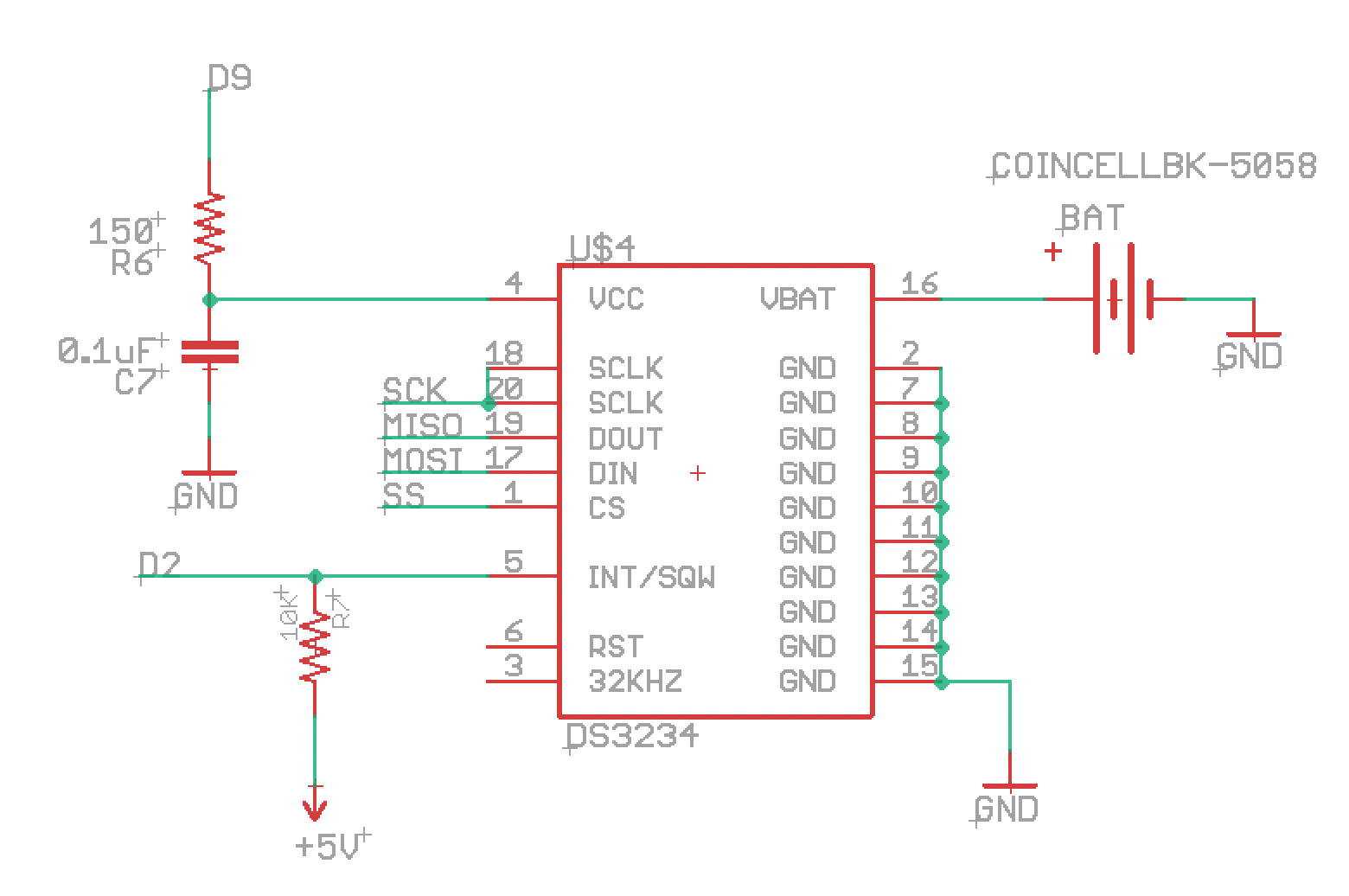
I see what you mean on how to do it. Will I need R6 in front of the RTC’s supply? I’m not sure what it does, other than someone said to put it there years ago when I asked about powering down the RTC with an arduino pin.
I don't see anything in the datasheet showing a series resistor like R6, so I doubt it's necessary.
Now when powering down the RTC it is running off battery. You can save your battery by connecting Vcc through a diode to the BATT pin, and another diode between the battery and the BATT pin to protect the battery of course. Now the circuit will autoselect battery or Vcc when the RTC is powered down.
It's also common to have a 100 nF cap on the BATT pin.
What is the purpose of C12 in your first schematic?
ShermanP:
I don't see anything in the datasheet showing a series resistor like R6, so I doubt it's necessary.
Ok, thanks.
wvmarle:
It's also common to have a 100 nF cap on the BATT pin.
thanks, I'll add that in.
I'm not sure about C12 in my LCD shutoff circuit. Who ever helped me make that 7 years ago had it there. Back then I hardly understood mosfets. I don't know a lot more now, but I can't say I see the purpose of C12. I just thought it perhaps some kind of decoupling cap?
It could be intended as decoupling - but a MOSFET doesn't need that. It could of course be intended for decoupling something else entirely but then it's placed rather awkwardly.
C12 cannot do any harm. More decoupling is "always" better.
R6 limits inrush current into C7 which may be important when an I/O is used to power the RTC. It is probably not needed when moved to the LCD (it surely has its own decoupling caps anyway) and powered via the MOSFET. If I were worried about inrush current I would increase R11. 1k or even 10k. Of course R10 must be also increased or better moved to the other side of R11 (connect it to the Arduino pin instead of MOSFET gate).
wvmarle:
Now when powering down the RTC it is running off battery. You can save your battery by connecting Vcc through a diode to the BATT pin, and another diode between the battery and the BATT pin to protect the battery of course. Now the circuit will autoselect battery or Vcc when the RTC is powered down.
Not sure I understand the need for the diodes. The datasheet says the RTC automatically switches between Vcc and Vbat, and always runs on Vcc if it's present.
If powered via the VCC pin, it uses a lot more current (~100 uA) than when powered through the VBAT pin (~3uA). The trick is using Vcc supply to power the VBAT pin when you disconnect the VCC pin of the chip. The I2C interface is down when you do that, but the ALM pin should still be active.
Now you basically have three choices. Power from Vcc supply (e.g. a pin set HIGH) to the VCC pin; Vcc supply to VBAT pin when Vcc is available, and finally battery as backup.
Yes, that's Ed Mallon's Cave Pearl mod. I didn't realize that's what you were describing. My problem with that is the voltage drop across the battery diode, which could have the effect of having to replace the battery more often. However in his case I think he runs ths DS3231 on system power almost all the time, so it really never has to use battery backup, and the voltage drop isn't an issue.
I guess I would prefer to just power down Vcc except when doing I2C, and let the coin battery take over. Current drain would only be a couple microamps, and at that rate a CR2032 would last a long time.
ShermanP:
Yes, that's Ed Mallon's Cave Pearl mod.
Never heard of that name.
The diode voltage drop should not cause the battery to last shorter, really. Especially when using Schottky diodes.
My cr2032 at 325mAh should last about 10 years if it’s used all the time, so I won’t have to worry about that part of it.
wvmarle:
Never heard of that name.
The diode voltage drop should not cause the battery to last shorter, really. Especially when using Schottky diodes.
Here's the video on his mod of the popular DS3231 module. He actually lifts and grounds the Vcc pin on the chip, then does your diodes. Apparently everything works fine, including I2C, when running from Vbat - so long as the pullups are powered during I2C.

I've never seen any explanation for the huge difference in current drawn by Vcc vs Vbat. There appears to be no functional difference in the operation of the RTC.
I thought the I2C interface would be down when the chip is powered over VBAT. That would to me explain why there's such a current use difference. But indeed, the datasheet confirms it:
"The I2C interface is accessible whenever either VCC or VBAT is at a valid level."
And another interesting bit:
"When using the device with the VBAT input as the primary power source, this pin should be decoupled using a 0.1μF to 1.0μF low-leakage capacitor. When using the device with the VBAT input as the backup power source, the capacitor is not required."
Indeed there appears to be no difference, to the extent that the datasheet suggests it's perfectly fine to use VBAT as primary power input!
Yes, that seems to be the case. But there's no explanation of what the extra Vcc current is used for. The only explanation I've ever seen that made any sense is that the comparators that test Vcc vs Vpf vs Vbat aren't needed when there's only Vbat so they may be turned off.
Still strange that those comparators need an order of magnitude more current than the rest of the chip... and even draw a copious amount of current for a comparator.
The comparators need "only" about 100 uA. That is reasonable current for a moderately fast comparator. You don't need nano-power comparator because it is assumed 100 uA from Vcc is negligible but you need quite fast comparator to prevent a glitch on changeover (and also prefer simple one to keep cost low).
For comparison AVR comparator consumes about 70 uA.
And there would have to be two comparators at least. You have Vpf (power failure) which is an internal reference, Vcc and Vbat. Anyway, looking at the datasheet logical diagram, the Power Control section is the only part affected by Vcc vs Vbat. If that's actually true, then maybe the comparators would be the explanation. Perhaps the comparators are powered only from Vcc.
This topic was automatically closed 120 days after the last reply. New replies are no longer allowed.