Powering the Pro Micro Leonardo

I have only been working with Adruino for a few months now. My first project suddenly came to a full stop.

I have a working prototype on the desk now with an Ebay relay board and an Ebay RS232 Receiver. The system reads serial commands and closes relays per my first Sketch.

I got a lot of help from this forum.

I have had some power problems with my ProMicro Arduino from the start. I didn't understand the 3.3V vs 5V business. There is a pad that says "Closed for 5V Open for 3.3V". Well, that doesn't seem to be necessary. My little test system is running from my Windows USB port just fine. I measure 4.6V at VCC on the ProMicro as well as on the RAW pin. That makes sense to me though I should have a little drop across the input diode.

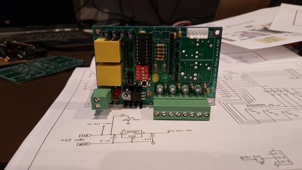
Ultimately, I want to run the board from 12vdc. My understanding is that I can feed 12v to the RAW pin and the onboard regulator will be happy and make me 5V at VCC. My current schematic is attached.

I made a PCB and tested everything I could before plugging in the ProMicro.

As soon as I plugged in the ProMicro, something snapped near the Regulator and the input diode. I didn't see exactly what. However, the ProMicro doesn't work any longer.

I only bought two of these (I have a couple more on order from Ebay) so I am not anxious to blow up another one.

I remember reading someplace that some of the less expensive manufacturers had been delivering ProMicro Leonardos with the diode backwards. It doesn't look like mine is backwards.

So am I missing something? Shouldn't I be able to apply 12V to Pin 12 of the ProMicro?

Here is a little description of my schematic..

12Vdc comes in. It heads for Adruino pin 24, my 7805 and to the coils of my 4 relays. My 5V regulator powers my Max232 RS232 receiver.

I have a little dip switch with pullups that I decided to power from the VCC on the Arduino but I know that wasn't necessary. I should have plenty of power. There are a couple of other LEDs that get directly driven from the Arduino.

The relay drivers are those little mos fets that are designed to driver relays with logic. Its like an npn Q but no resistor or clamping diode is necessary. I have used these many times. They should be fine.

It occurs to me that I can just jumper 5V from my own regulator and power the Adruino from VCC instead of applying 12V to RAW. I don't know why I didn't do that originally but that's not the current configuration.

Is it better for me to run the ProMicro from 5V connected to VCC?

Is the RAW pin really designed to take 12VDC?

I would appreciate any thoughts.

Greg

The specifications on the SparkFun Pro Micro say that you can apply up to 16V to RAW. Depending on where you got yours from, that may not be true for your version.

Yes, it's usually safer and better to use your own 5V regulator to supply all the 5V components on your board. Those little tiny regulators on the Pro Mini can't take a lot of current at 12V before they are toasted.

The "closed for 5V" jumper is related to the running voltage of the chip on the Pro Micro. It should not be necessary for you to touch that. It should be done at the factory.

Actual maximum voltage depends on the component (5V linear regulator) that was actually installed when the board was manufactured.

You would need to inspect that specific part number and find the manufacturer's associated datasheet and find the maximum input voltage rating. Parts may vary depending on production runs and parts availability.

The Pro Micro is a SparkFun Electronics design and details found here.....

You can supply 5V to the RAW pin and it should work just fine. VCC pin is intended for supplying regulated 5V to low current components like sensors.

borland:
... You can supply 5V to the RAW pin and it should work just fine. ...

You probably won't get 5 volts out in that case. Raw should be no less than 6 volts in order to get 5 volts out of the MIC5219 voltage regulator

I guess it is a safe test to power the PM with regulated 5v at the RAW pin. Electrically, its the same as powering it from the USB. If it can run with 5V USB power, it should be able to be run with my own 7805 from there.

I am not too worried about blowing up another PM but I really do not want to damage my laptop USB port.

I love experimenting but I am hoping to have a device that can run 24/7 and safely be reprogrammed while in the PCB.

G

gmcmurry:
I guess it is a safe test to power the PM with regulated 5v at the RAW pin. Electrically, its the same as powering it from the USB.
...

USB bypasses the voltage regulator if it's set up as a 5 volt board (solder pads connected.) Raw goes through the VR either way. There is a voltage drop from the regulator. So putting 5 volts into RAW will result in the board operating at 4-ish volts. It will probably work just fine. Be aware that Microchip only claims that it will work properly down to 4.5 volts. Use your meter to check the voltage if you are concerned.

But to your original point, it wasn't low voltage that caused the "something snapped near the regulator" effect. My guess is that something was wired wrong, and that your chip saw 12 volts. The "snapped" part was probably one of the large capacitors near the GND and VCC pins, but if the 32u4 itself was exposed to 12 volts, the board is toast.

I am sure the board is toast... No question.

Its really a mystery about the "solder pads". None of the boards I have seen, sold as 5V, have them connected and the boards work fine from USB. While powered up, I can measure about .5 volts between the pads.

Would 3.3 volt / 8mhz boards have a 16mhz xtal ? So, if the pads are open, wouldn't we expect to see an 8 mhz xtal on board?

I am sure I will blow a couple more boards before I understand this fully. I see also, how one cannot rely on much consistency with how these boards are made.

Thanks for helping me understand.

G