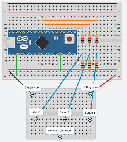
I am new to Arduino and don't have much experience with electronics. I am trying to use an Arduino Nano with a remote so that I can click the button using the digital I/O pins (D1, D2, D3).
This is my current setup,
- My Arduino Nano 3.3 is connected to my mac machine through USB. I am using pyfirmata to turn the digital pins HIGH/LOW
- The remote runs on two 1.5v battery = 3V. I have connected 3.3v from Arduino to remotes battery +ve and Arduino ground to remote battery -ve.
- The remote buttons are two concentric circles (image attached) which gets shorted when the physical button on the remote is pressed.
- I have a wire running from the inner circle to the digital I/O pin through a voltage divider using a 1KΩ and 2KΩ resistor which produces about 3.18V
When the remote turns on there is an LED that blink for 1 sec
- SETUP 1: If I plug the USB with D2, D3, D4 connected the remote doesn't turn on or none of the buttons work
- SETUP 2: If I plug the USB with D2, D3, D4 not connected then the remote turns ON and all buttons work manually
- SETUP 3: If I plug the USB with D2, D3, D4 not connected and then connect D2, D3, and D4 after its ON it can be controlled through Arduino IO pins. Pin LOW on D2 taps the Button 1 and HIGH releases it for example.
In SETUP 1 using a multimeter I can see that there is 3.35V running across the remote battery +ve and -ve .
Any thoughts on what could be wrong in this setup or any heap on how to debug it will be greatly appreciated?
Thanks in advance


