Hey all, I have been tasked with a project to create a pressure transducer with an Arduino Uno R3. I have been working on it for a while now, and I believe that I am close. However, I am stuck on receiving a legitimate pressure reading.
To start off with this explanation, I am currently using a breadboard, Arduino Uno R3, PendoTECH Single-Use Pressure Sensor (PRESS-N-038), INA125P (instrumentation amplifier), ILI9341 (Adafruit Display Screen), and an ADS1115 (Adafruit ADC) as my components in this system. From the research that I've done, these are all compatible with each other.
What this system does is it outputs a voltage, which is then converted into a pressure. There must be a baseline voltage/pressure to reliably find the pressure corresponding to the delta in voltage. I will now explain my circuit, and as I go, I'll explain what each component is contributing to the overall circuit.
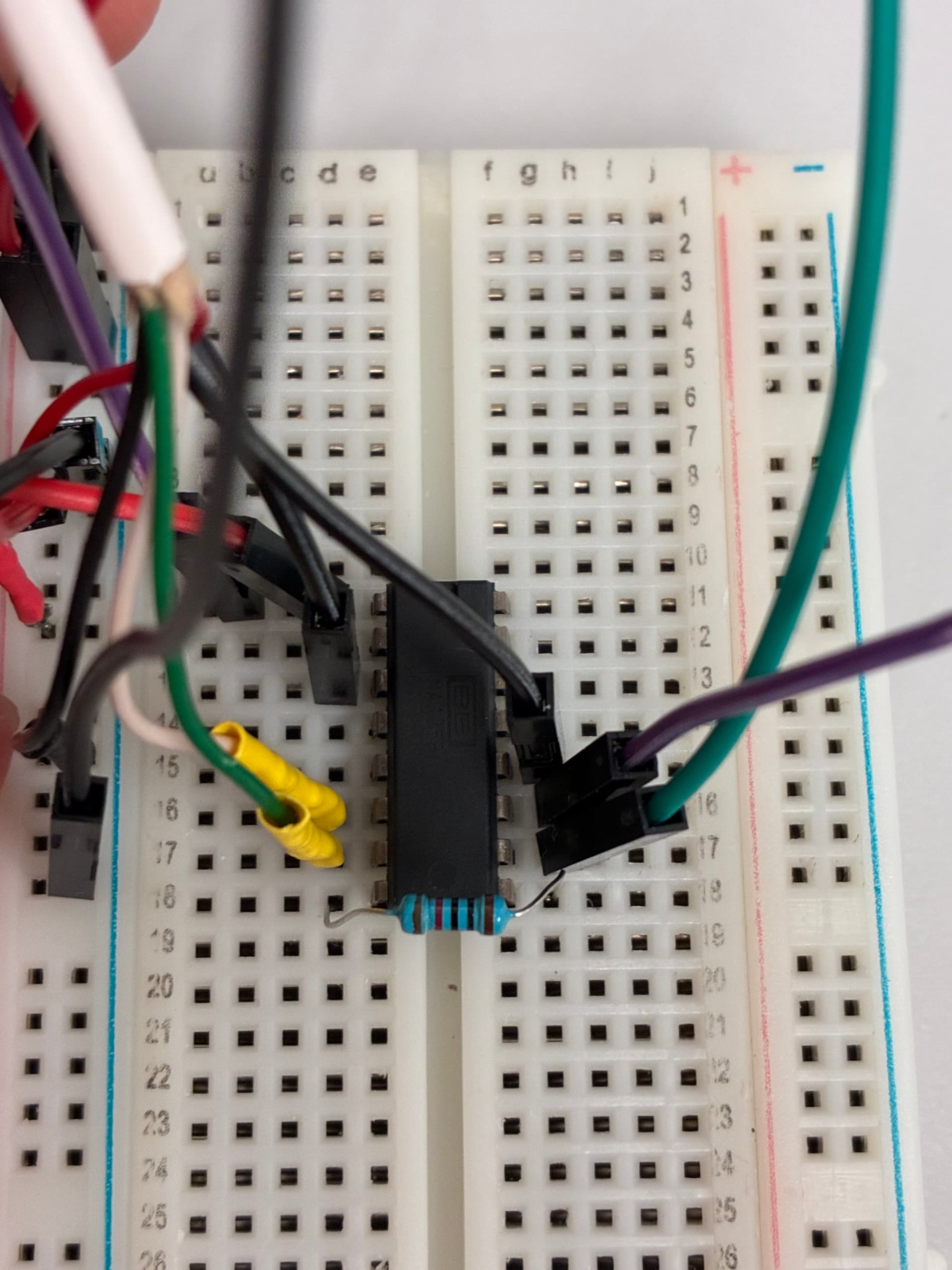
The Arduino Uno R3 is the mastermind behind the circuit. It is USB-connected to my computer for 5V of power. I then have the Arduino wired to the power rails on the breadboard to power the components in the circuit. The next component in this circuit is the INA125P to amplify the signal coming from the pressure sensor. Without the INA125P, the pressure sensor would have too small of a signal when powered at 5V. It would be too small for the ADC (ADS1115) to read with the INA125P. It helps to amplify the signal to a readable range. This increased reading varies based on the resistor you set at pins 8 & 9 (referenced from the pin diagram). I currently have a 10k ohms resistor, but I have also tried 1k. The INA125P also helps convert the input from differential (measures from pins 6 & 7) to a single-ended reading. Since I'm only taking one reading at a time, this is more practical. In the picture labeled "INA125P Wired", it shows how I've wired the INA125P (obviously :)). I will now explain what each wire goes to. At the top left of the amplifier (pin 1), I have it connected to the power rail, where it gets its power from the Arduino. Pin 3 is connected to the GND rail. Pin 6 is connected to the signal+ from the pressure sensor. This pin is the Vin+ while pin 7 is the Vin-, which is connected to the signal-. Pins 8 & 9 are connected with a resistor, which controls gain and amplification. Pin 10 (Vout) is connected to the ADS1115's A0 pin. This wire is the output of the amplifier (the final product that is then digitized to show a number on a display. Pin 11 is called Sense, and it's tied back to 5V (pin 1) as an output reference feedback loop. Pin 12 is the Voltage Reference COM, and it is connected to GND to ensure an accurate reading.
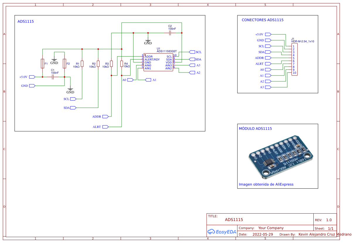
The ADS1115 helps convert the reading from analog to digital, and without this converter, the resolution and accuracy of the reading wouldn't be nearly as good. This means that smaller pressure changes (smaller changes in voltage) can be detected with the ADS1115. This small device connects to the Arduino with the SDA/SCL pins. SDA goes to SDA, and SCL goes to SCL. You could also use A4 and A5 on the Arduino, but for simplicity, I chose SDA and SCL.
I have made sure the screen works, but recently, I have not had it wired in the system because I've been focusing on getting an accurate reading from the pressure sensor. This is where my problem arises. I can't get a change in voltage, but I have verified that my sensor works, and I have used a multimeter at every pin, and they have all been in the ranges that they are supposed to be. For example, I connected my multimeter probes between pins 6 & 7 to test the pressure sensor, and at no pressure applied, it should be a few mV (it was). When I applied pressure, it ideally is supposed to rise to roughly 12-20 mV (it rose into that range). The pressure sensor is working while plugged into the circuit! I continued to check pins for ideal ranges. They all seemed to be where they needed to be. I can't seem to figure out why that voltage/pressure change isn't reaching the output. If anyone has any ideas or input, I'd appreciate your help.
Also, at the moment, I have only used simple scripts in Arduino to test the function of my screen and the pressure sensor circuit before I start putting everything together. I've used multiple variations, but they are all similar to this script:
#include <Wire.h>
#include <Adafruit_ADS1X15.h>

Adafruit_ADS1115 ads;

void setup() {
  Serial.begin(9600);
  ads.begin(); // Defaults to address 0x48

  // Optional: set gain (PGA), affects input voltage range
  // GAIN_ONE = ±4.096V (best match for 0–5V system)
  ads.setGain(GAIN_ONE);
}

void loop() {
  int16_t adc0 = ads.readADC_SingleEnded(0);

  // Convert ADC value to voltage
  float voltage = adc0 * 4.096 / 32767.0;

  // Sensor scale: 0.2584 mV/V/psi @ 5V = ~1.292 mV/psi
  // With gain ~10 → ~12.92 mV/psi
  float mV_per_psi = 0.2584 * 5.0 * 10.0; // ≈ 12.92 mV/psi
  float pressure_psi = (voltage * 1000.0) / mV_per_psi;

  Serial.print("ADC: ");
  Serial.print(adc0);
  Serial.print(" | Voltage: ");
  Serial.print(voltage, 5);
  Serial.print(" V | Pressure: ");
  Serial.print(pressure_psi, 2);
  Serial.println(" psi");

  delay(1000);
}
Note: I have tried setting the gain to something higher, and it hasn't helped my case. As I said, this is a simple test to see if the pressure is being outputted correctly.
Once again, if you have any input on this problem, I'd greatly appreciate your guidance. Thank you in advance!