Hello! I am trying to use this Primary & Secondary (Master & Slave) tutorial to make one Arduino Uno send signals to the other. I understand that you need to connect the grounds of the two Arduinos to make this work. When I connect the grounds, however, the servos connected to the Secondary/Slave become uncontrollable and jittery. Will you please help me solve this problem?
If you help us solve the problem, we’ll certainly try.
Code, schematic, detailed parts list…..
2 Likes
Possible EMI (Electromagnetic Interference) Issue
This sounds like it could be related to EMI, either conducted or radiated. While I can't confirm this is the problem without more information, I also can't rule it out. Most MOS logic circuits are fast and sensitive to edge transitions. Minimizing lead lengths (which act as antennas) to less than 10 inches (25 cm) is crucial, as longer leads can pick up frequencies up to about 750 MHz, not accounting for reflections and other effects.
Tips to Reduce EMI:
- Keep Connections Short: Both transmitters and receivers are affected by antenna length—longer antennas have greater gain and can pick up more interference. Use the KISS principle: Keep It Short & Simple.
- Avoid Parallel Lines: Ensure power and logic lines are not running parallel to each other to minimize crosstalk and interference.
1 Like
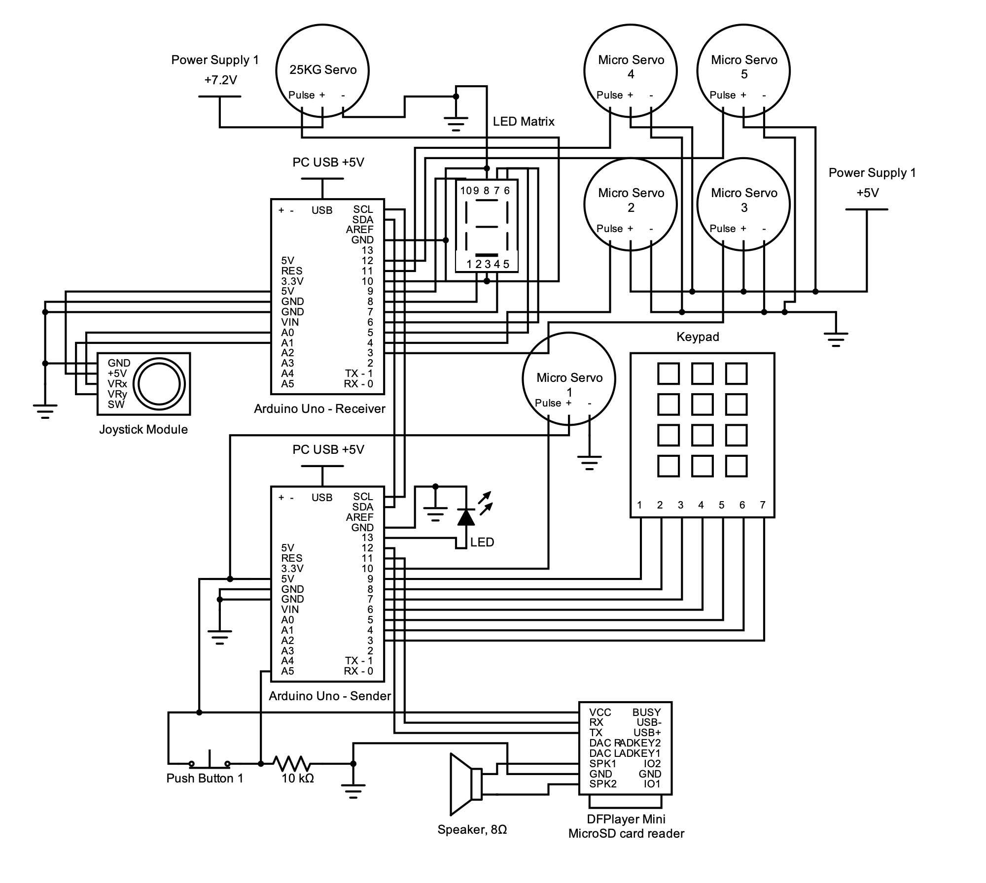
Thank you! Here is my current schematic for the whole system. The Arduinos work fine with their respective I/O when their grounds are not connected, but when they are, all I/Os, especially the servos, act up.
Thank you for the information! The wires for the servos are all bunched together with a twist tie; do you think that would cause the interference?
Here is my current schematic for reference.
The tutorial video didn't use servos, but I have tried using this technique before with servos on a different circuit and it worked with no issues. I'm trying to use all these components together to accept inputs on the Primary Arduino and output them to the servos on the Secondary Arduino. I'm curious if any of my components may be causing interference?
What’s your +5 supply, and powering Servo 1 from the ’Arduino’s +5V output pin isn’t a good idea.
Can you show a photo with the wires ?
I suggest to not turn it on anymore. If you want to try the I2C bus between two Arduino boards, then remove all the servo motors and remove the extra power supplies.
The led and the 7-segment display need resistors.
It is not clear how the GND from the power supplies is connected.
Pin SDA and SCL are the same as pin A4 and A5. They are connected on the board. You have a push button connected to SCL on the Sender board. Pin 10 of the Receiver board seems to be connected to GND and to pin 3 of the display and to the Servo motor.
The video and the article on the dronebotworkshop website is informative, but there are mistakes. My main concern is how the I2C bus is used. It puts you on the wrong path. The I2C bus is not used to send text. Using it together with the String object in a interrupt routine is not good. Reading a single byte in a while-statement to keep the last byte is nonsense.
The pullup resistors on the I2C bus are missing (at least in the schematic).
A suitable value is 4K7 ohms.
GND must be common to both ONE's.
1 Like
Starting with I2C Signal Issues:
Your I2C lines are likely acting like antennas, turning on and off due to floating signals. Without proper pull-up resistors, the lines can only rely on leakage currents to maintain a high state, which is insufficient for stable operation.
Solution: Add Pull-Up Resistors:
- Add two pull-up resistors, typically 4.7kΩ, to the I2C data lines.
- One resistor on SCL (Serial Clock Line)
- One resistor on SDA (Serial Data Line)
These resistors will help maintain proper signal levels, ensuring reliable communication between your I2C devices. Follow @MaximoEsfuerzo guidelines.
1 Like
If you really want to understand the principles of exchanging data between two Arduino UNOs, then perform one task at a time like:
1. Connect two UNOs as per Fig-1.
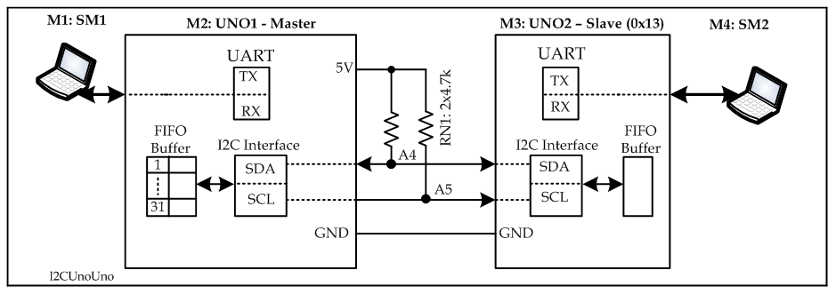
Figure-1:
2. Create and upload sketches on both Master and Slave to check that the Master finds the Slave at I2CSlaveAddress at 0b0010011 (0x13).
3. add codes with the sketches of Step-2 tto exchnage data bytes 0x23 and 0x56 between Master and Slave.
4. Add Keypad with Master. Add codes withe seketches of Step-3 so that the data item 1234 entered from the Keypad will be shown om SM2 of Fig-1.
5. and so on......
6. The attached file may worth reading and practicing.
Ch-7I2CLec.pdf (334.4 KB)
1 Like
Thank you for the suggestion. This particular micro servo has almost no load and only moves within about 15 degrees; do you still think a separate power supply is needed? It's more or less used as a visual signal.
My power supply is 6xAA 1.2V rechargeable batteries. The raw output is 7.2V, which I use to power the 20kg servo, and for the remaining four micro servos, I have a voltage regulator that brings the 7.2V down to 5V.
This is awesome, thank you so much!

Okay, thank you! I updated the wiring diagram to add the resistors, does this look good?
No good! Check with Fig-1 of post #12 for pull-up resistors with I2C Bus.
1 Like

This solved the servo jittering, thank you so much! I suppose if you're using the SDA and SCL pins, you can't have anything wired or mapped to A4 & A5, correct?
Okay, I'll look at the datasheets and example schematics for the matrix and implement them.
I have all grounds from both Arduino boards connected, but I isolated the grounds for the five servos powered by the external power supply.
That was an export error, sorry about that. I fixed the diagram with multiple suggestions made on this thread; only pins 3 & 8 of the LED matrix are supposed to be connected to ground:
A cheap small servo motor can have a stall current of 0.5A. When it starts to turn, then it can request a peak current that is close to the stall current. You need to have that 0.5A ready for a servo motor.
Buying a "strong" servo motor is not good, it is bad, because they need a lot of current. I think that your circuit should be able to give a peak of 5A for that servo motor.
This is a common problem from someone who starts to use servo motors. The idle current or the average current is much lower than the stall current, yet the circuit should be able to deal with the stall current.
Keep in mind that your project might fail. The I2C bus has weak signals and it is not really meant for communication between processors. As soon as motors are added to a project, then the weak I2C bus might have troubles with the noise and current peaks through wires. Sometimes the whole project has to be re-wired and keeping the sensor and I2C signals away from power signals. The high current peaks that go through the servo motor have to find their way back to the power supply. That ground current can disturb the I2C bus. Grounding is a craftsmanship on its own.
Adafruit says about the cable length: "So what can you get away with? In true hacker spirit - just try it and find out!" here: https://learn.adafruit.com/working-with-i2c-devices/cable-length#suggested-approach-3110954
When I read that, then I read that everyone should stop using the I2C bus.
It seems like there’s a misunderstanding or overgeneralization regarding the use of the I2C bus. While I2C is not suitable for every application, it remains widely used and reliable for many purposes, particularly for short-distance communication between multiple peripherals and microcontrollers.
Key Points About I2C:
- Intended Use: I2C is designed for communication over short distances within the same circuit board or between closely placed modules. It’s ideal for connecting sensors, EEPROMs, RTCs, and other peripheral devices to microcontrollers.
- Common Misapplications:
- Long Distances: I2C is not well-suited for communication over long cables or between devices far apart due to signal degradation and noise susceptibility.
- High-Speed Requirements: I2C's speed (typically up to 400 kHz for standard applications) may not be sufficient for high-speed data transfer needs, such as video signals or high-frequency data streams.
- Challenges with I2C:
- Pull-up Resistors: Proper pull-up resistors are crucial for stable communication. Incorrect values or missing resistors can lead to signal integrity issues.
- Bus Conflicts: Because I2C is a shared bus, miscommunication or conflicts can arise if not properly managed, especially with multiple devices.
- Noise Sensitivity: I2C lines are susceptible to electromagnetic interference (EMI), which can cause errors in noisy environments.
- When I2C is a Good Choice:
- Small Systems with Close Components: I2C excels in small projects where sensors and microcontrollers are close together.
- Low-Speed Sensor Integration: It’s great for interfacing sensors, displays, and other low-speed peripherals that don’t require long communication lines.
Conclusion:
There’s no need to abandon I2C altogether; it’s a valuable tool when used in the right context. The key is to understand its limitations and use it appropriately. For applications where I2C might not be the best fit, consider alternatives like SPI (for faster communication) or UART (for longer-distance serial connections).
2 Likes