Hi,
ich wollte fragen, ob mir jemand behilflich sein könnte, um zwei Arduinos und einen Servotreiber über I2C kommunizieren zu lassen. Bis jetzt kommunizieren nur die zwei Arduinos.
Leider weiß ich nicht, wie genau nun ich die Verkabelung zum Servotreiber machen muss (+ welche Widerstände). Wäre echt gut, wenn mir jemand dabei helfen könnte.
Ich habe folgende Schaltung (unrelevantes entfernt):
Mein Code für Arduino "1" ist folgender (unrelevantes entfernt):
#include <Wire.h>
#include <Adafruit_PWMServoDriver.h>

//Lenken
#define PWM_FREQUENCY_HZ 60      // Frequency of PWM signals
#define PCA_CHANNEL_SERVO 0      // Board PCA9685: servo channel
#define PWM_SERVO_CENTER 390     // Neutral position in 0..4095
#define PWM_SERVO_MAX_DELTA 120  // Max. +/- deviation from neutral position


// PWM servo driver module
#define PWM_CHANNEL_ESC 1
#define PWM_NEUTRAL 400
#define PWM_DRIVE 415
#define PWM_BACKWARDS 380

Adafruit_PWMServoDriver pwm = Adafruit_PWMServoDriver();

//Lenken
int minPulse = PWM_SERVO_CENTER - PWM_SERVO_MAX_DELTA;
int maxPulse = PWM_SERVO_CENTER + PWM_SERVO_MAX_DELTA;

char distance_Char[] = "V"

void setup() {
  Wire.begin();  // join i2c bus (address optional for master)
  Serial.begin(9600);

}

void loop() {

  pwm.setPWM(PWM_CHANNEL_ESC, 0, PWM_DRIVE)
  Serial.println(distance_Char);
  Wire.beginTransmission(4);          // transmit to device #4
  Wire.write(distance_Char);  // sends five bytes
  Wire.endTransmission();             // stop transmitting

}
Mein Code für Arduino "2" (unrelevantes entfernt):
#include <SoftwareSerial.h>
#include <Wire.h>

SoftwareSerial BT(4, 2);

char myChar;

void setup() {
  BT.begin(9600);                // set the data rate for the SoftwareSerial port
  Wire.begin(4);                 // join i2c bus with address #4
  Wire.onReceive(receiveEvent);  // register event
  Serial.begin(9600);
  pinMode(8, OUTPUT);
}
void loop() {
  while (BT.available()) {
    myChar = BT.read();
    if (myChar == 'V') {
     Serial.println("Hi")
    }
  }
}

void receiveEvent(int howMany) {
  int charCount = 0;
  while (Wire.available()) {  // loop through all but the last
    char c = Wire.read();     // receive byte as a character

    if (c == '#') {
      BT.println("Hi");
  }
}
Anhand Ihres Diagramms fällt mir als Erstes auf, dass Sie die GND-Verbindung zwischen den beiden Arduinos vermissen. Ich hoffe, dass es in der echten Hardware-Verkabelung sowieso nicht fehlt.
Das zweite Problem besteht darin, dass Sie den V+-Pin des PCA9685 nicht an Arduino anschließen sollten, da dies die Stromversorgung für die Motoren ist und Arduino diese nicht direkt mit Strom versorgen kann (Sie benötigen eine externe Quelle und schließen diese an die beiden Schraubanschlüsse V+/GND an ).
Um auf Ihre Frage zurückzukommen: Da I2C eine busbasierte Kommunikationsleitung ist, müssen Sie lediglich alle SDAs und SCLs miteinander verbinden (SDA mit der grünen Leitung, SCL mit der gelben), dann werden beide normalerweise mit zwei Pull-up-Widerständen verbunden auf 5V.
Sobald Sie fertig sind und die Hardwareprobleme überwunden haben, können Sie über das Codieren sprechen.
PS: Entschuldigung für etwaige Fehler, ich schreibe Deutsch und meine Antwort wurde automatisch aus dem englischen Forum übersetzt, in dem Sie sie zuvor gepostet haben ...
The receiveEvent() runs in a interrupt. Using the Serial library from a interrupt routine should be avoided. It will work, but use it only for testing. You use the SoftwareSerial library from a interrupt. That is bound to go wrong in more than one way.
Wie genau muss ich diese zwei Widerstände anschließen? Welchen Wert sollten die haben?
Könnten Sie mir vielleicht ein passendes Beispiel zeigen oder eine Skizze?
In the onReceive handler, read the data and store it in a buffer or variable and set a flag to notify the something is received. In the loop(), that flag can be checked and the data in the buffer can be used.
#include <SoftwareSerial.h>
#include <Wire.h>

SoftwareSerial BT(4, 2);

char myChar;
char buffer;
bool flag = false;

void setup() {
  BT.begin(9600);                // set the data rate for the SoftwareSerial port
  Wire.begin(4);                 // join i2c bus with address #4
  Wire.onReceive(receiveEvent);  // register event
  Serial.begin(9600);
  pinMode(8, OUTPUT);
}
void loop() {
  while (BT.available()) {
    myChar = BT.read();
    if (myChar == 'V') {
      Serial.println("Hi")
    }
  }

  if (flag == true) {
    flag = false;
    if (buffer == '#') {
      BT.println("Hi");
    }
  }
}

void receiveEvent(int howMany) {
  while (Wire.available()) {  // loop through all but the last
    char c = Wire.read();     // receive byte as a character

    buffer = c;
    flag = true;
  }
Yes, like that.
You can make the flag "volatile", because it is used both in the interrupt and the loop().
volatile bool flag = false;
You test the buffer after releasing the flag. New data could be in the buffer when printing it if there was a onReceive interrupt right at that moment.
If you release the flag after finished with the buffer, then you can check in the onReceive handler if the previous buffer was used and set an error if not.
volatile bool flag = false;
int error = 0;

void loop() {
  if (flag)
  {
    if (buffer == '#')
    {
      BT.println("Hi");
    }
    flag = false;    // ready with buffer, release the flag
  }
}

void receiveEvent(int howMany)
{
  if (howMany == 1)     //  a single byte is expected
  {
    if (flag)
    {
      error++;          // the flag was still raised
    }
    else
    {
      buffer = Wire.read();
      flag = true;
    }
  }
}
Do you see how the flag is used now ? If it was not released yet, the new data is not accepted and the error is set. In the loop() you can check for an error.
I change the receiveEvent(). If only 1 byte is expected, then I would like to check that, for extra safety.
A 'bool' variable is true or false. A condition is also true or false. You can simplify the condition in the if-statement.
So you can do this:
bool sunshine = true;
bool rain = false;
if (sunshine and !rain)
{
  Serial.println("Nice weather");
}
Die Widerstände sind "pull-up". Dieser Begriff bedeutet, dass sie ein Signal "heraufbringen", wenn kein Element vorhanden ist, das es auf Vcc (+5 V oder +3,3 V, je nach typ) oder GND bringt. Ein "pull-up" ist daher ein Widerstand, sagen wir mindestens 10 kOhm, zwischen dem Pin und Vcc:
Dennoch sind auch in dem Beitrag Fehler enthalten, die man unbedingt vermeiden muss.
Da wird der I2C Bus mit 3,3 Volt und 5 Volt in einem Beispiel vermischt.
Ob das wirklich so toll ist, möchte ich bezweifeln.
Interface Two Temperature Sensors with Different I2C Addresses
At first and before working with sensors with the same I2C address, we are going to work with some sensors with different I2C addresses to get more familiar with the subject. Then we go to the main part, which would be working with sensors sharing the same I2C address.
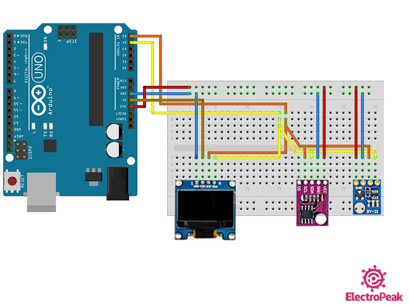
Step 1: Circuit
The following circuit shows how you should connect the two temperature & humidity sensors GY-21 and LM75 and also the OLED display to the Arduino Board. Connect wires accordingly.
As you can see in the image above, all three module support I2C communication protocol. A4 and A5 pins of the Arduino Board are the SDA and SCL pins, respectively. These two pins differ from microcontroller to microcontroller, and even from Arduino Board to Arduino Board. For more information, you can check this link.