Hi everyone ![]()
Can you help me with this printer encoder pinout?
I want use it with arduino and i connect pins to board but not work


I test with this encoder worked well


Thank everyone ![]()
Hi everyone ![]()
Can you help me with this printer encoder pinout?
I want use it with arduino and i connect pins to board but not work
I test with this encoder worked well
Thank everyone ![]()
Eh?
Provide a drawing including what the part is connected to and how it's all wired together. Hand-drawn, photographed, pasted into reply box.
Hi thanks for answering
And sorry for my English ![]()
I forget this photo
I connect those pins directly to leonardo board
But not worked out
Can the problem be resistance and capacitor? so that it is connected in an encoder that works ![]()
Provide a drawing including what the part is connected to and how it's all wired together.
LEt's start over from the top.
What did the encoder do in the printer? How do you know it is an encoder and not just a paper sensor to tell the printer that paper is present in that location?
Hi,
This device of yours is a strip encoder for canon G2800 G2000 G3800, just like this one.
Hi,
I have several of these sensors removed from old printers that I got from friends.
The ones that are marked in red look like yours.
I already damaged some by connecting wrongly.
On one side they have an IR LED and on the other they have an IC that
detects the IR and amplifies the signal.
It is important not to connect the wrong IC, because connecting it wrong can damage it.
The PDF below shows more internal details of the sensor.
Optical_Sensor.pdf (251.5 KB)
I don't know what's your mean ![]()
![]()
Can you explain me or send a sample please?
Sorry
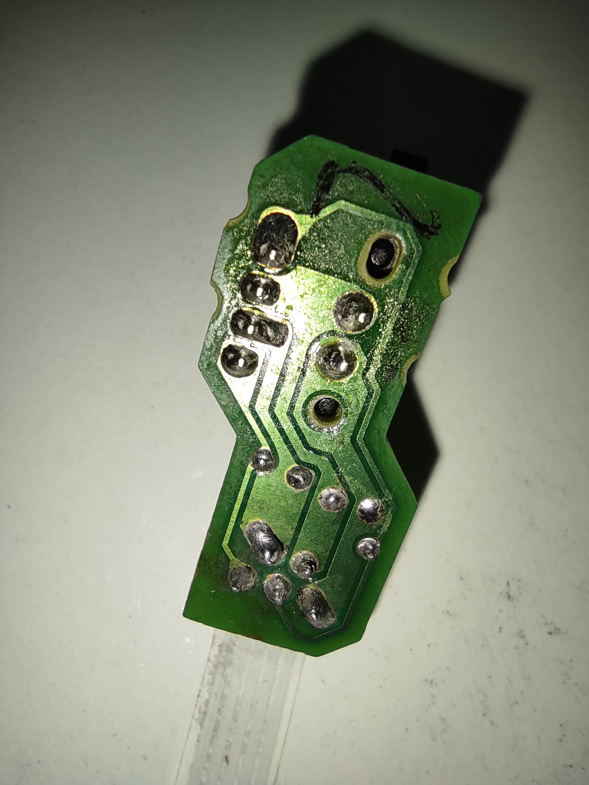
Hi thanks for reply
But i buy it from an store and he told me its a encoder with signal disk
And i search about it in google
And its look like the other one encoder and same pins on the main hardware but without resistor and capacitor ![]()
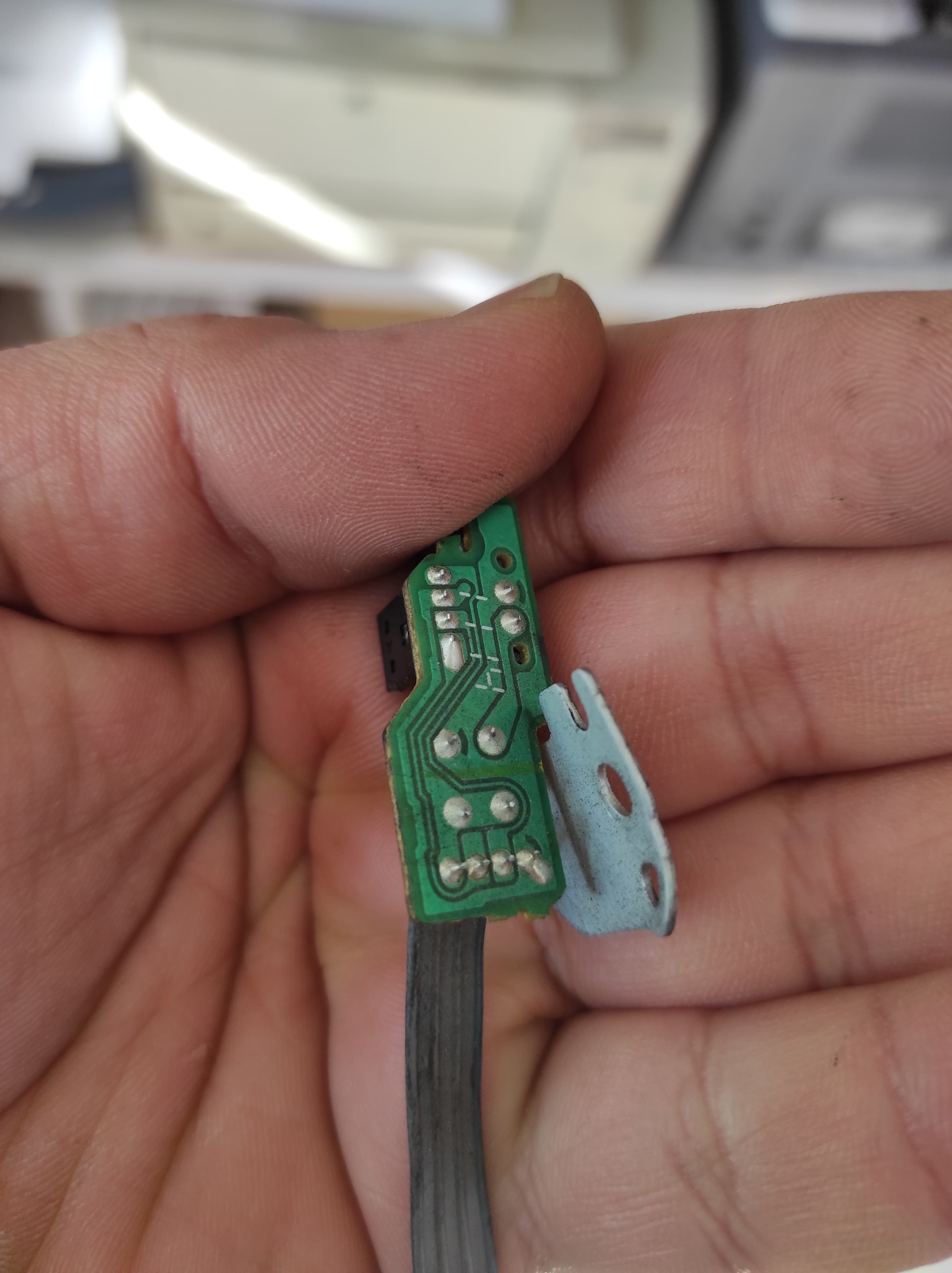
Hi thanks for reply
Yeah its look like them but I can't run it
Yeah i think connect them wrongly ![]()
But do you know IR LED work 5V or 3.3V?
The other one work with 1k ohm resistor on one side ( 5V ) and i think it's connected to IR LED pin
And a capacitor connected to both GND pins ( I don't know the capacitor value ![]() )
)
Hi,
A LED does not work with a specific voltage, but with current.
With a 1K resistor as shown, there will be no problem with the LED,
because it must support currents in the order of 20 to 50 mA, and 5V with 1K allow currents of a maximum of 5 mA.
I think the voltage for this LED should be around 12V,
to allow a current of at least +- 12 mA.
As for the IC side, from the photo I can't determine which pins are signal and which are power.
I connected it to ardouino leonardo ![]()
First 3.3v and then 5 volt without resistor ![]()
I think mised up ![]()
![]()
That gonna help?![]()
This encoder work perfectly with arduino Leonardo
Show, graphically, how the sensor is connected to the Arduino including power and ground. Hand drawn is OK. Include pin names and numbers of both devices (if known).
Note: this does NOT mean a schematic you copy/pasted from somewhere else. Show a representation of what is in front of you.
Sorry bro
Did you see the photo i sended ?![]()
Hi,
If it works then what's the problem?
Bro I can't do graphically , sorry
I don't know how to do this
But i showed you how to connected pins to Arduino leonardo
I connected exactly like this photo to the board
Hi
This encoder ( without resistor and capacitor ) not work
And this encoder (with resistor and capacitor) work fine
I want use the encoder which don't have resistor and capacitor ![]()
Hi
Sorry bro
Can you help please?
Thanks
This topic was automatically closed 180 days after the last reply. New replies are no longer allowed.


