Hello, just basic questions that I can hopefully have answered. I have a brain injury, so trying to understand a similar but not the same get me all weird inside. I am starting fresh and am trying to see if this will be a feasible task for me to finish.
I have some pro micro boards and my ultimate goal is to use a button box I have already 3d printed to emulate keystrokes (I.e. flip toggle switch up = Shift + A)
My box has 12 toggle switches, 6 momentary buttons, 4 rotary encoders, 2 potentiometers.
Can I use the pro micro with switches and buttons to mimic keystrokes or hot keys?
Can I connect the amount of buttons/switches/pots/encoders to a single board?
I’m assuming I can wire some switches in line to connect say, 6 buttons, to a single pin on the board?
This will be for DCS, but I want kind of a universal button box instead of having to switch to different boxes for different aircraft.
Thanks in advance, I might need some things broken down Barney style, but really just seeking answers to those questions for now.
That is more than a Pro Micro can handle without additional hardware. Based on your description, I suggest that you add shift registers(74HC165) or I2C/SPI port expanders for your toggles and buttons.
you can dedicate one switch to choose mode in which Box will start, keyboard or joystick/gamepad. additional(or intead of this) you can setup Xpadder.exe (buttonBox must be in joystick/gamepad mode) that all other switches will be key extenders, and for buttons assign some keystrokes or whole text strings(macros)
I think it might be possible, without any extra chips.
How many pins does each switch have?
Do these also have momentary push switches built in and do you wish to use them?
I am thinking as follows:
Rotary encoders can be difficult to read without missing movements, especially when not moved slowly. So 4 external interrupt pins and 4 regular digital input pins would be used. The built-in momentary push buttons will be dealt with later.
Clearly the 2 potentiometers will require one analog input each.
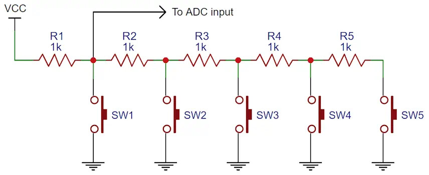
For the 12 toggle switches, these could be split into 2 groups of 6 and each group connected as part of R 2R ladders to 2 more analog inputs. 18 resistors required, of 2 different values.
So far, that's 12 pins used which include 4 analog inputs and 4 external interrupt pins. 6 Pro micro pins remain.
This leaves the 6 momentary push buttons and the 4 momentary push buttons of the encoders. These could be wired as a 10-to-4 encoder using 16 diodes, assuming only one of the buttons would be pressed at a time.
Alternatively, the 10 momentary buttons could be wired using more resistors to another analog input.
I like the toggle switches on an R2R digital to analog converter as an analog input.
I would build and test that part first; without doing anything to be sure, I think the chances of success will be enhanced by using good switches and matched or higher precision resistors.
I did a reasonable R2R ladder with one value resistor, using two in parallel for the R resistors, I had a bag of forget the ohms but enough so I was able to get a good set to use.
When I had more time than money. :-|
I turned up just now a few suggestions to buffer the toggle switches ahead of the ladder.
But that starts to raise the question of whether offloading some of the cleverness to a simple I/O expander wouldn't be a better kind of fun to get working.
Nice to see any Arduino board maxed out, be it pins, memory or processing power.
This is extremely helpful! Yes, the rotary encoders do have a momentary push button in them. As for the toggle switches:
5 (on) off (on), which are 3 pin.
3 on off, 2 pin.
4 (on) off, 2 pin.
Would the rotary encoder only work to emulate the same keystroke or hot key each turn? Or is it programmable to say, turn a dial left and right?
Sorry for the delay. Here are pictures of how the panels are set up for now. And links to all the switches on this box, there’s a lot… I have no idea about forum etiquette either, apologies. Links in multiple replies since I’m a new user.
@PaulRB --- I note that he has more than 1 Pro Micro and from when I was a flight simmer I know that more than 1 stick device at a time can be used at least back in the WinXT days. I didn't have DCS but did run IL2 as far as Maddox took it.
On a single Pro Micro, matrix wiring a 6x6 might handle a fair number of digital contacts but with the mix of switches given, how many could be matrix digital inputs?
I note that stacking switches on an analog means analog read speed and only 1 can be closed at a time or do I have that wrong?
Switching analog pins takes time to clear the pin so 210 micros just to read 1 set of switches, but the whole set!
Could the rotaries be dedicated to a second Pro Micro if need be?
Back in the day I have plugged 2 mice into my gaming box and moved one side to side and the other up and down, the mouse pointer moved in circles.
I still had a Saitek X52 and throttle quadrant then before I got too slow to game effectively. When you can't energy-fight, you become a mud hen, time to hang it up!
Yes, I have 3 pro micros. I have 3 nanos also which I think I might have to end up using with the rotary and pots, trying to stay away from DCS BIOS and have a more universal controller. The box I printed is pretty big, and in 2 pieces. I might use 2 boards to power everything. I know absolutely nothing about any of this, but it seems like that would be the easiest route?
Having the 3 way switches and the 3 way momentary switches is kind of what I’m worried about. All the posts I have read revolve around those switches either constantly repeating, or not registering in the off position.
I will have to wire in resistors and diodes into the matrix correct? Especially when every switch in that matrix will be doing something different? I can’t get my words to my fingers but I’m sure someone understands what I’m saying.
I just asked this question because I overlooked the end of your post of course haha. Each switch will have a resistor and a diode? If say 6 toggle switches are in a matrix, the diode will cut off the signal to prevent repeated keystrokes?
Figuring out if all these switches and buttons can be read by a single pro micro will take some further thinking.
The first two types of toggle switch you posted links to seem the same as each other to me (except the colour, which is not relevant). They are SPST so not suitable for the R 2R resistor matrix I suggested. But maybe some other arrangement will be possible.
The momentary (ON)-OFF toggle switches can be read in the same way as a pushbutton, so could be combined with the standalone pushbuttons and encoder pushbuttons into a matrix or diode-encoder circuit.
I'll post another reply when I have more time to think through the options.
Just diodes, so that multiple buttons/tpggles can be closed at the same instant. Input shift registers might be preferable to matrix and might not.. PaulRB and other hardware gurus could say.
Arduino pins have an Input mode that supplies weak 5V through in-chip resistance, saves having to wire pull-down resistors!
3-ways could be wired as more than one switch and handled in software, I'm pretty sure. A matrix can be scanned at 40 to 50 switches per ms not counting debounce which even then you can't move fast enough to get lag effects. Hardware debounce might be done with one capacitor (maybe resistor too) but it's possible to do in under 10 ms in software using non-blocking code.
They're not audio quality but still, $1.30 ea! I'm not sure if Futurlec is still in bidness, haven't bought from them in years.
The travel seems longer than the number, amazing trimmers!
I suffered clots to the head after medical trauma in 2000. It is rough to say the least! In time you may recover and find that re-learning one thing allows what you thought was gone finds pathways back! I do miss online flight sims and my squad!
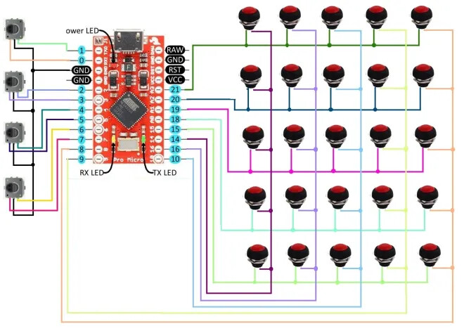
how encoders are connected:
this left enough pins for matrix 5x5,
if 2 pins goes to 2 potentiometer then left pins enough for button matrix 4x4;
each 3-way switch take 2 pins, so this list:
17 momentary pushbuttons & toggle switches (including those on the rotary encoders)
2 pots
4 rotary encoders
2 on-off toggle switches
3 on-off-on toggle switches
22 pins, Micro Pro have 18. at least 3x 3-way switches need to be on analog pin as resistor array. they are such:
or such