I am a newbie so would be grateful of any help
I purchased 10 pro micro boards from aliexpress for a project I am building.
This is the full description of the items I bought
Pro Micro ATmega32U4 5V 16MHz Original Chip Replace ATmega328 For Arduino Pro Mini For Leonardo UNO R3
I wanted to program them to run a rotary encoder which requires 5v. I should also mention they would be connect to a pcs USB port at the time.
I thought these boards vcc output should be 5v. But after having problems I tested the vcc and was getting 3.3v I contact the supplier but was told I had tested it wrong. Can someone please confirm if I should be getting 5v from the vcc pin or if I am doing something wrong.
I will include 2 photos 1 with me testing it and 1 of the board if you need any more info just let me know.
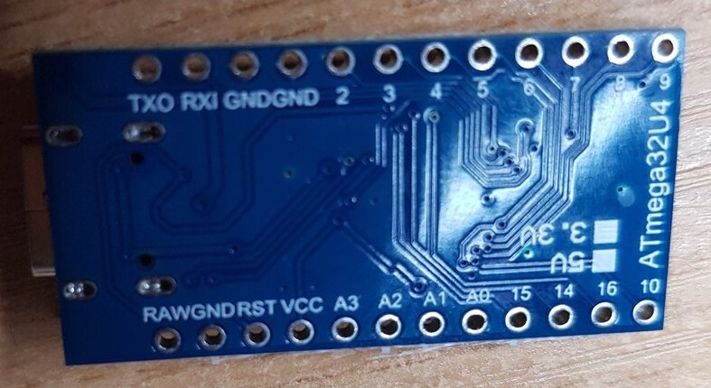
The Arduino Pro Micro is available in two versions: 3.3V and 5V, and the operating voltage determines the maximum allowable voltage on the I/O pins:
3.3V: Runs at 8 MHz, which is half the speed of the 5V version. The supply voltage (VCC) is 3.3V, and the supply voltage (RAW) is 3.6V–12V.
5V: Runs at 16 MHz, and is similar to an Arduino Leonardo.
Arduino Pro Micro Pinout, Power Supply and Brief Schematic ...
You can check the back corner of the board to determine which version you have. One of two boxes should be checked to indicate the operating voltage.
Thank you so much for taking the time to reply.
I tried taking a photo of the items you circled but couldnt get a clear enough photo
So here is what it says on the one chip it says
SCTF
16.000
and on the other chip it says
AAEU
NAQ1
Hope that helps. I would just like to know if I have been sold the one I ordered and if the order is correct which one should I have ordered to have 5v from the VCC
Thank you so much I have bridged the J1 jumper with solder and I am now getting the correct 5v from the VCC pin.
I guess its my own fault for buying cheap boards but fantastic to know I can still use them.