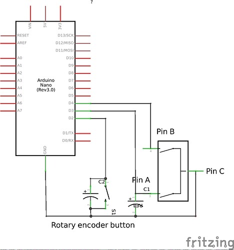
Hello. I need to use a rotary encoder in a project that involves menus displayed in a I2C LCD.
I bought one and tried to make it work with some codes from internet. None of them worked for me so I tried to guess it by using the code below.
My encoder has a button and 5 pins. I don't have the model number so I couldn't find the datasheet. It does not come in a module.
In the code below I attached interrupts to pins 2 and 3, and i connected them to the pins A and B of the rotary encoder.
I connected the pin C to ground.
#include <Arduino.h>

struct state {
	int a, b;
};

void isr();

void setup() {
	pinMode(2, INPUT_PULLUP);
	pinMode(3, INPUT_PULLUP);
	Serial.begin(115200);
	attachInterrupt(0, isr, CHANGE);
	attachInterrupt(1, isr, CHANGE);
}

void isr() {
	state buff = {digitalRead(2), digitalRead(3)};
	Serial.print(buff.a ? 'H' : 'L');
	Serial.println(buff.b ? 'H' : 'L');
}

void loop() {
}
And the output was like this:
When I turned the encoder clockwise once:
LH
LH
HH
HH
When I turned the encoder counterclockwise:
LL
LL
HH
HH
So I decided to use only an interrupt in A and detect the next state after a HH. If it was LH, the encoder was turning clockwise; if it was LL, it was turning counterclockwise. I implemented that in this code.
#include <Arduino.h>

struct state {
	int a, b;
};

void isr();
void button();

state prev = {1, 1};
int counter = 0, butcounter = 0;
bool change = true, but = false;
unsigned long t = 0;

void setup() {
	pinMode(2, INPUT_PULLUP);
	pinMode(3, INPUT_PULLUP);
	pinMode(4, INPUT_PULLUP);
	Serial.begin(115200);
	attachInterrupt(1, isr, CHANGE);
}

void isr() {
	state buff = {digitalRead(3), digitalRead(4)};
	if (!(buff.a && buff.b)) {
		if (prev.a && prev.b) {
			if (!buff.a && buff.b) {
				counter++;
				change = true;
			} else if (!buff.a && !buff.b) {
				counter--;
				change = true;
			}
		}
		prev = buff;
	} else {
		prev = {1, 1};
		t = millis();

	}
}

void button() {
	if (millis() > t+500) {
		but = true;
	}
}

void loop() {
	if (change) {
		change = false;
		Serial.println(counter);
	} else if (but) {
		but = false;
		Serial.println();
		Serial.print(++butcounter);
		Serial.println(". Button!");
		Serial.println();
	}
}
And connected the arduino nano as it is shown in the image attached.
The encoder worked fine, the counter increased when I turned it CW and decreased when it went CCW. The button also worked. Then I used it in my project and connected it the same way. It worked for a while and then stopped. When I used the code above to test it once more, it didn't work properly. I connected the pin A to pin 2 and pin B to 3 and attached at both interrupts in CHANGE mode. To my surprise the B pin was changing all the time and most of the time it was low. A day later the encoder worked for a while and then happened the same. My question is: Am I using the rotary encoder correctly? If I'm not, how is it supposed to be used?
Is the encoder broken?
I'm sorry if I've written too much but I wanted to detail it as much as possible. Thank you!

