When I plug everything in, the LEDs come on full power but the pots won't dim them. I double checked all connections and it's hooked up as shown.
I thought I used 10K pots, but I get 2.52K between the legs. At the endpoints between the legs and wiper I got 0, 2.52 and then the opposite endpoint, 2.52, 0. But between the endpoints I got numbers like 3.04, 3.11. Which adds up to more than double 2.52, but I still got 2.52 between the legs. Seems odd. It seems like I should still get a dimming effect, even if it were choppy. I used a fine adjustment 20-25 turn pots.
My plan is to get the dimming to work, then add a RTC, then work on a sunrise sunset effect. Is that a good way to build a sketch? This is lighting for a fish tank.
int nemLED = 3; //
int nemPOT = A1;
int rightrockLED = 5;
int rightrockPOT = A2;
int leftrockLED = 6;
int leftrockPOT = A3;
int purpLED = 9;
int purpPOT = A4;
int FANS = 4;

void setup() {
  // put your setup code here, to run once:
  pinMode(nemPOT, INPUT);
  pinMode(nemLED, OUTPUT);
  pinMode(rightrockPOT, INPUT);
  pinMode(rightrockLED, OUTPUT);
  pinMode(leftrockPOT, INPUT);
  pinMode(leftrockLED, OUTPUT);
  pinMode(purpPOT, INPUT);
  pinMode(purpLED, OUTPUT);
  pinMode(FANS, OUTPUT);

}

void loop() {


  analogWrite(nemLED, (analogRead(nemPOT)/ 4));
  digitalWrite(nemLED, HIGH);

  analogWrite(rightrockLED, (analogRead(rightrockPOT)/ 4));
  digitalWrite(rightrockLED, HIGH);

  analogWrite(leftrockLED, (analogRead(leftrockPOT)/ 4));
  digitalWrite(leftrockLED, HIGH);

  analogWrite(nemLED, (analogRead(nemPOT)/ 4));
  digitalWrite(nemLED, HIGH);

  analogWrite(purpLED, (analogRead(purpPOT)/ 4));
  digitalWrite(purpLED, HIGH);

  digitalWrite(FANS, HIGH);
My plan is to get the dimming to work, then add a RTC,
You can break that down a little further... Write some code to dim one LED without the pot, then some code to dim another LED, etc.
If you are going to make a sunrise/sunset effect, it's not clear to me why you need pots at all.
But if you want to check the pots and your wiring, run the [u]Analog Read Serial Example[/u]. (You can modify the code to read different pots, one at a time.)
I thought I used 10K pots, but I get 2.52K between the legs. At the endpoints between the legs and wiper I got 0, 2.52 and then the opposite endpoint, 2.52, 0. But between the endpoints I got numbers like 3.04, 3.11. Which adds up to more than double 2.52, but I still got 2.52 between the legs
Make sure you are measuring the pot out of the circuit.
This is lighting for a fish tank.
Your drawing shows 200W of LEDs. That's 200W of heat and probably enough light for a swimming pool! (Maybe the equivalent of 1000W of incandescent light.)
The pot value doesn't matter... Half-way is half-way, etc. A lower pot value will draw more current and a higher pot value will tend to pick-up more noise.
Both halves of the pot MUST add-up to the total resistance.... A pot is ONE resistor with a sliding tap. (Audio pots are not linear, so at the center position the resistance isn't divided 50/50 but the two halves still sum to the total. You don't have audio pots because they don't make multi-turn audio pots.)
Jiggy-Ninja:
Why are you doing digitalWrite() immediately after analogWrite()? Get rid of them.
DVDdoug:
Get rid of both digitalWrite() and analogWrite()? I lifted this from another sketch and modified it-I thought it would work...
You can break that down a little further... Write some code to dim one LED without the pot, then some code to dim another LED, etc.
If you are going to make a sunrise/sunset effect, it's not clear to me why you need pots at all.
But if you want to check the pots and your wiring, run the [u]Analog Read Serial Example[/u]. (You can modify the code to read different pots, one at a time.) Make sure you are measuring the pot out of the circuit.
Your drawing shows 200W of LEDs. That's 200W of heat and probably enough light for a swimming pool! (Maybe the equivalent of 1000W of incandescent light.)
The pot value doesn't matter... Half-way is half-way, etc. A lower pot value will draw more current and a higher pot value will tend to pick-up more noise.
Both halves of the pot MUST add-up to the total resistance.... A pot is ONE resistor with a sliding tap. (Audio pots are not linear, so at the center position the resistance isn't divided 50/50 but the two halves still sum to the total. You don't have audio pots because they don't make multi-turn audio pots.)
The dimming and sunrise/sunset are independent. I need the dimming and only want sunrise/sunset. The tank is sunlit, so as winter approaches, I ramp up intensity. (A few months in the summer I shade the tank a bit) It is a lot of light, but will use full intensity for only a few weeks per year. Reef tanks need lots of quality light. BTW, there are cooling fans on the LEDs, I didn't show them because I got them to work as expected.
A couple reasons pots are more attractive to me are, it's a hard for me dealing with code, plus I don't have a device to change things around wirelessly and I don't want to pull the Arduino and take it to my computer every time I change intensity, which will be weekly.
Yeah, I thought the two readings from a pot should add up to total resistance-IDK what the heck's going on with that.
Why dont you make it more interesting and automated, for instance instead of potentiometers use photoresistors, which you can put outside?
int photoresistor_1 = analogRead(A0);
photoresistor_1 = map(photoresistor_1, 0, 1023, 255 , 0); // should be inverted since the stronger the light the lower the resistance
notoriousg:
Why dont you make it more interesting and automated, for instance instead of potentiometers use photoresistors, which you can put outside?
int photoresistor_1 = analogRead(A0);
photoresistor_1 = map(photoresistor_1, 0, 1023, 255 , 0); // should be inverted since the stronger the light the lower the resistance
analogWrite(1, photoresistor_1);
That is an interesting idea, thanks but I need to keep this as simple as possible.
Is there a way to test the LDDs, pots and LEDs for dimming without the Arduino hooked up? It would be nice to eliminate the hardware as a potential problem.
Thanks Jiggy, I'll give that a try in the morning.
Meanwhile, I disconnected the Arduino pins and unplugged the power supplies from the wall.
I put one probe of my DMM (set at 20K) in the terminal block connected to the wiper and the other end to ground. Turning the pot one way took me to 0. Turning it the other way the pots climbed to 2.79-3.02, then dropped to 0.96 and would drop no further.
Then I did the same thing on the 5V line-with a different result!???
Turning one way way took me to 0. Turning the other way climbed to 3.36-3.51, then dropped to 2.51 and would drop no further.
The 5V line was isolated but the ground is connected to the 12V PS, the 36V PS, the LDDs and Arduino. I can't imagine what else might explain that discrepancy.
It just occurred to me that the 2.51 number is because I have 4 10K pots in parallel. Does that sound right?
Jiggy, I lost the digital write and now have dimming! Great call, thanks a ton! (:
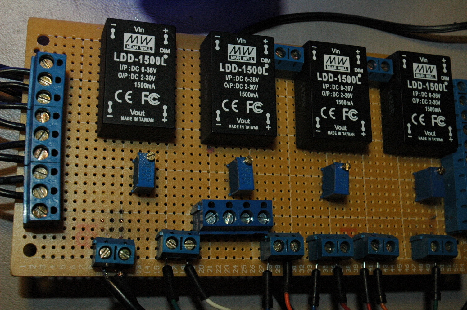
Tom, Here's a pic of the project with lights dimmed way down and another as close as I could get to the pots.
Right now, the connections at the Arduino are skinny little breadboard wires inserted into a header. The connection seems kind of iffy to me. should I plan to solder directly to Arduino after I get an RTC and sunrise/sunset working?
I read your 1st comment gave a quick look at the code (very quick) you trying to use
pots to dim the leds, why you don't use map function?
Easy and fast to use, add your pots to analog inputs, put your leds to digital pwm, map them both
255 - 1023 and you are done, I read that you want to add a RTC as well and light up your leds, dim, like
sun rise or sun set, build a function to determin the exact time you want to do, make a 2nd function
to automatically light them up and off at the sun rise/set, and that's all.
I looked for a map function tutorial and could not find a straight up 'this is how it's done'. This code dims the LEDs with the pots. Is there a problem with using this as the base and working from there?
void setup() {}

void loop()
{
  int val = analogRead(0);
  val = map(val, 0, 1023, 0, 255);
  analogWrite(9, val);
}
Basic Example with One pot and One led.
int led = 2; //PWM Pin
void setup() {
pinMode (led, OUTPUT);
}

void loop()
{
  int val = analogRead(0); // Analog pin A0 Pot
  val = map(val, 0, 1023, 0, 255); // Pot value from 0 to 1023 and led value from 0 to 255
  analogWrite(led, val); //While the pot value will change so the led value will do as well (%)
  /* Think about it as %, the map will divide for you the values and you will get % output, if
       you turn the pot at 20% so the led will go 20% brightness..so on.
 */
}
After that you can add more and more pots or leds as this example.
Using the RTC
int led = 2;
void setup() {
pinMode (led, OUTPUT);
}

void loop()
{
  int val = analogRead(0);
  val = map(val, 0, 1023, 0, 255);
  analogWrite(led, val);

   RTC_SunRise/Set();
}

void RTC_SunRise/Set(){

  /* Add your RTC data/time/minits/hours..etc depends how your RTC Lib works.

*/
     //Sun Rise example
    if (time > "06:00" ){ // the set of time here all depends how your lib works
       int sunRise = time;
        sunRise = map(sunRise, 0, 59, 0, 255); //again all depends how your lib RTC works, making minits maping with the led, same as pot but we use minits instead of pot.
     }
}
And that's the basic coding using map, pot, led and rtc.