Problem moving 13 servos to switch defined position with Mega Adafruit PCA 9685

My project uses 13 servos. I want to use the Adafruit i2c PCA 9685 board to connect the servos (for ease of installation wiring)

I am using an Ardunio Mega board to handle the data.

Pins 0 - 12 are each connected to the common of a toggle switch, which in turn is connected either side to a preset pot with the wiper of each pot connected to one side of a switch.

The center (common) of the switch goes into the analogue input of the Mega. Toggling one way (or the other) provides a user defined voltage to the analogue pin (depends on the pot setting - its configured as a voltage divider with the wiper position giving the value to the Mega)

The Mega / Adafruit i2c PCA 9685 works fine when I run a test program which sweeps the servos through their full arc. (ie the comms and servos are working ok)

When I use the code below, the program executes the code servos 0 -3 work and go to their set position, but then all servos start chattering (move through perhaps 5 deg arc at random)

I can use 4 servos without problem - as soon as I plug the others in its an issue.

I have checked the current being drawn from the power supply and the combination draws 870ma at peak.

What am I doing wrong?

#include "HCPCA9685.h" // Include the HCPCA9685 library created by Andrew Davies

#define I2CAdd 0x40 // Default address of the PCA9685 Module

#define PotA A0 // Pot pin connected to A0 
#define PotB A1 // Pot pin connected to A1 
#define PotC A2 // Pot pin connected to A2 
#define PotD A3 // Pot pin connected to A3 
#define PotE A4 // Pot pin connected to A4 
#define PotF A5 // Pot pin connected to A5 
#define PotG A6 // Pot pin connected to A6 
#define PotH A7 // Pot pin connected to A7 
#define PotI A8 // Pot pin connected to A8 
#define PotJ A9 // Pot pin connected to A9 
#define PotK A10 // Pot pin connected to A10 
#define PotL A11 // Pot pin connected to A11 
#define PotM A12 // Pot pin connected to A12 
// Used to store the mapping of the Pot values

int ServoA;
int ServoB;
int ServoC;
int ServoD;
int ServoE;
int ServoF;
int ServoG;
int ServoH;
int ServoI;
int ServoJ;
int ServoK;
int ServoL;
int ServoM;

HCPCA9685 HCPCA9685(I2CAdd); // Define Library to use I2C communication

void setup() 
{
HCPCA9685.Init(SERVO_MODE); // Set to Servo Mode

HCPCA9685.Sleep(false); // Wake up PCA9685 module
}


void loop() 
{
int val1A = analogRead(PotA); // Read current value of PotA
int val1B = analogRead(PotB); // Read current value of PotB
int val1C = analogRead(PotC); // Read current value of PotC
int val1D = analogRead(PotD); // Read current value of PotD
int val1E = analogRead(PotE); // Read current value of PotE
int val1F = analogRead(PotF); // Read current value of PotF
int val1G = analogRead(PotG); // Read current value of PotG
int val1H = analogRead(PotH); // Read current value of PotH
int val1I = analogRead(PotI); // Read current value of PotI
int val1J = analogRead(PotJ); // Read current value of PotJ
int val1K = analogRead(PotK); // Read current value of PotK
int val1L = analogRead(PotL); // Read current value of PotL
int val1M = analogRead(PotM); // Read current value of PotM

// Map Pot values to servo Min and Max position 
ServoA = map(val1A, 0, 1023, 10, 420); // Used to move Servo 0
ServoB = map(val1B, 0, 1023, 10, 420); // Used to move Servo 1
ServoC = map(val1C, 0, 1023, 10, 420); // Used to move Servo 2
ServoD = map(val1D, 0, 1023, 10, 420); // Used to move Servo 3
ServoE = map(val1E, 0, 1023, 10, 420); // Used to move Servo 4
ServoF = map(val1F, 0, 1023, 10, 420); // Used to move Servo 5
ServoG = map(val1G, 0, 1023, 10, 420); // Used to move Servo 6
ServoD = map(val1H, 0, 1023, 10, 420); // Used to move Servo 7
ServoI = map(val1I, 0, 1023, 10, 420); // Used to move Servo 8
ServoJ = map(val1J, 0, 1023, 10, 420); // Used to move Servo 9
ServoK = map(val1K, 0, 1023, 10, 420); // Used to move Servo 10
ServoL = map(val1L, 0, 1023, 10, 420); // Used to move Servo 11
ServoM = map(val1M, 0, 1023, 10, 420); // Used to move Servo 12


// Move Servos to read postion from pot
HCPCA9685.Servo(0, ServoA); // Move Servo 0 
HCPCA9685.Servo(1, ServoB); // Move Servo 1
HCPCA9685.Servo(2, ServoC); // Move Servo 2
HCPCA9685.Servo(3, ServoD); // Move Servo 3
HCPCA9685.Servo(4, ServoE); // Move Servo 4
HCPCA9685.Servo(5, ServoF); // Move Servo 5
HCPCA9685.Servo(6, ServoG); // Move Servo 6
HCPCA9685.Servo(7, ServoH); // Move Servo 7
HCPCA9685.Servo(8, ServoI); // Move Servo 8
HCPCA9685.Servo(9, ServoJ); // Move Servo 9
HCPCA9685.Servo(10, ServoK); // Move Servo 10
HCPCA9685.Servo(11, ServoL); // Move Servo 11
HCPCA9685.Servo(12, ServoM); // Move Servo 12- Turn Table
delay(100);
}
}
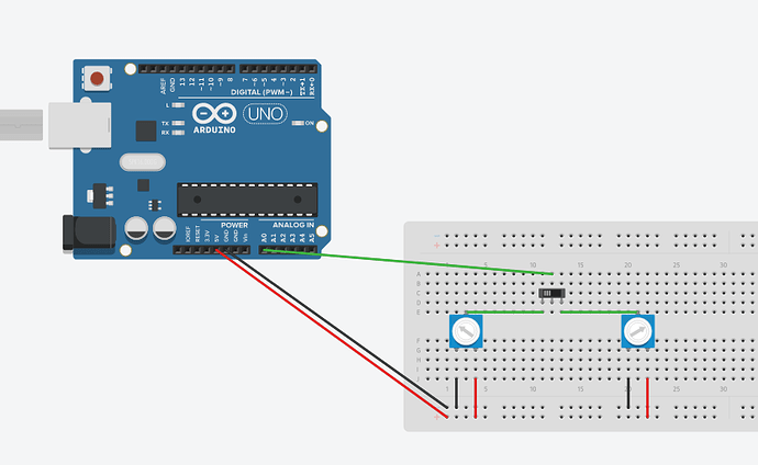
I think you should attach a schematic.

Not certain what is the best package to provide circuit drawings for this forum.

However a simple idea of the connections for the input side is shown in the image attached below (I know its a UNO and slider switch that is shown - but the principle with the Mega and toggle switch is the same) The input design is the same for 13 inputs. The outputs are servos connected to the PCA 9685 board which communicates via i2c with the Mega

Image from Reply #2 so we don't have to download it. See this Image Guide

...R

Thanks Robin - I could not see where to get the image URL from to imbed

Hi,

Can you please post a copy of your circuit, in CAD or a picture of a hand drawn circuit in jpg, png?

Please include you power supplies, a hand drawn diagram is 10 times better than a fritzy picture when it comes to diagnosing circuits.

What are you using to power the servo's?
Can you post spec/data of the servo please?

Thanks... Tom... :slight_smile:

Is it the idea that the toggle switch can connect either one of two preset pots to an analogPin?

And is setting on the preset pot intended to define the angle the servo is to move to?

If so, I can't understand the role of pins 0-12 in your Original Post - or do you mean A0 to A12?

If this was my project I would change this

int val1A = analogRead(PotA); // Read current value of PotA
int val1B = analogRead(PotB); // Read current value of PotB
int val1C = analogRead(PotC);

to

int val1A = analogRead(PotA); // Read current value of PotA
val1A = analogRead(PotA);
int val1B = analogRead(PotB); // Read current value of PotB
val1B = analogRead(PotB);
int val1C = analogRead(PotC); 
val1C = analogRead(PotC);

so as to read each pin twice and discard the first reading which may have remnants of the previous ADC value

Also I would use arrays to greatly shorten the code and reduce the risk of typos. Something like

for (n = 0; n < numServos; n++) {
  adcVal = digitalRead(potPins[n]);
  adcVal = digitalRead(potPins[n]);
  servoVal = map(adcVal, 0, 1023, 10, 420);
  myServo[n].write(servoVal);
}

...R

Hi,

Thanks I will try that and let you know.

To answer your questions:

Is it the idea that the toggle switch can connect either one of two preset pots to an analogPin? YES

And is setting on the preset pot intended to define the angle the servo is to move to? YES

If so, I can't understand the role of pins 0-12 in your Original Post - or do you mean A0 to A12? My Typo - it should be A0 to A12

krc2015:
My project uses 13 servos. I want to use the Adafruit i2c PCA 9685 board to connect the servos (for ease of installation wiring)

Use your multimeter to measure the voltage between your arduino ground (at the arduino board itself), and the voltage of the 'ground' on your breadboard. make sure it's not a significant amount. Do this measurement for the case with your limited number of servos working (eg. 3 servos working)...... and do it again for the case when you have more servos connected - when the problem occurs.

And if a ground of 1 particular board should be tied to the ground of another board.... then look into that as well.

TomGeorge:
Hi,

Can you please post a copy of your circuit, in CAD or a picture of a hand drawn circuit in jpg, png?

Please include you power supplies, a hand drawn diagram is 10 times better than a fritzy picture when it comes to diagnosing circuits.

What are you using to power the servo's?
Can you post spec/data of the servo please?

Thanks... Tom... :slight_smile:

Thanks TG for looking, Will include a circuit diagram but its going to be late today before I get chance to do that.

The power supply is a 500w computer switched mode supply its us ed to power all parts of the circuit

The servo power supply is through a connection to the PCA9685 board - that connection is isolated from the logic level supply and is used to supply the servos 5 - 6v

The servo detail is shown below:

TowerPro SG90 Servo
Specifications

Modulation: Analog
Torque: 4.8V: 25.00 oz-in (1.80 kg-cm)
Speed: 4.8V: 0.12 sec/60°
Weight: 0.32 oz (9.0 g)
Dimensions: Length:0.91 in (23.0 mm)
Width:0.48 in (12.2 mm)
Height:1.14 in (29.0 mm)
Motor Type: 3-pole
Gear Type: Plastic
Rotation/Support: Bushing
Rotational Range: (add)
Pulse Cycle: (add)
Pulse Width: 500-2400 µs
Connector Type: JR

Southpark:
Use your multimeter to measure the voltage between your arduino ground (at the arduino board itself), and the voltage of the 'ground' on your breadboard. make sure it's not a significant amount. Do this measurement for the case with your limited number of servos working (eg. 3 servos working)...... and do it again for the case when you have more servos connected - when the problem occurs.

Thanks, the grounds seem good and the voltage difference between the three boards (Breadboard - Mega and PCA9685) is less than 0,0001v