I am using the serial monitor to command servo position. The serial monitor returns the position data, but the servos don't move. What am I doing wrong?
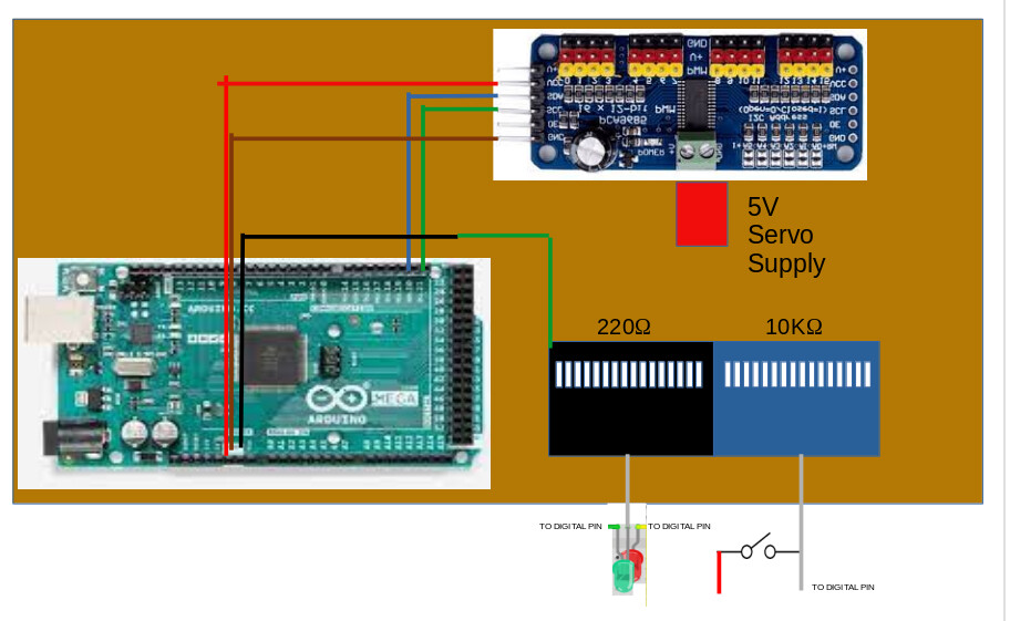
MEGA Power is being provided by USB. A separate power supply is connected to the PCA9865 for servo power, and yes the negative side is connected to the common ground. I am currently using only servo output 0.
The Servo Motor is an SG90. The PWM light comes on on the PCA9865 when I command a move using the Serial Monitor.
The wiring is standard for connecting a MEGA and a PCA9865. And yes I have tried different motors, and the hookup has been verified multiple times. The SG90 is rated at 4.8 - 6V, I started at the low end at 5V and I moved up to high end. No difference.
Servo motors can't possibly be powered by a PCA9865.
The SG90 requires about 700 mA just to start moving. Use a separate power supply (e.g 4xAA battery pack) to power the servo, and connect all the grounds.
a+ or a- where a is the desired position from a center of 1500. The monitor returns the new position. Update: I am able to control a SERVO directly with the MEGA, so I believe there is something wrong with the calibration code used with the PCA9865. The power for the two boards is through the USB Port. I wonder if I should use a separate power source for them as well?
This is confirmed to work for the first two servo positions:
/***************************************************
  This is an example for our Adafruit 16-channel PWM & Servo driver
  Servo test - this will drive 8 servos, one after the other on the
  first 8 pins of the PCA9685

  Pick one up today in the adafruit shop!
  ------> http://www.adafruit.com/products/815

  These drivers use I2C to communicate, 2 pins are required to
  interface.

  Adafruit invests time and resources providing this open source code,
  please support Adafruit and open-source hardware by purchasing
  products from Adafruit!

  Written by Limor Fried/Ladyada for Adafruit Industries.
  BSD license, all text above must be included in any redistribution
 ****************************************************/

#include <Wire.h>
#include <Adafruit_PWMServoDriver.h>

// called this way, it uses the default address 0x40
Adafruit_PWMServoDriver pwm = Adafruit_PWMServoDriver();
// you can also call it with a different address you want
//Adafruit_PWMServoDriver pwm = Adafruit_PWMServoDriver(0x41);
// you can also call it with a different address and I2C interface
//Adafruit_PWMServoDriver pwm = Adafruit_PWMServoDriver(0x40, Wire);

// Depending on your servo make, the pulse width min and max may vary, you
// want these to be as small/large as possible without hitting the hard stop
// for max range. You'll have to tweak them as necessary to match the servos you
// have!
#define SERVOMIN  150 // This is the 'minimum' pulse length count (out of 4096)
#define SERVOMAX  600 // This is the 'maximum' pulse length count (out of 4096)
#define USMIN  600 // This is the rounded 'minimum' microsecond length based on the minimum pulse of 150
#define USMAX  2400 // This is the rounded 'maximum' microsecond length based on the maximum pulse of 600
#define SERVO_FREQ 50 // Analog servos run at ~50 Hz updates

// our servo # counter
uint8_t servonum    = 0;
uint8_t servonumMax = 1;


void setup() {
  Serial.begin(9600);
  Serial.println("First 2 channels, Servo test!");

  pwm.begin();
  /*
   * In theory the internal oscillator (clock) is 25MHz but it really isn't
   * that precise. You can 'calibrate' this by tweaking this number until
   * you get the PWM update frequency you're expecting!
   * The int.osc. for the PCA9685 chip is a range between about 23-27MHz and
   * is used for calculating things like writeMicroseconds()
   * Analog servos run at ~50 Hz updates, It is importaint to use an
   * oscilloscope in setting the int.osc frequency for the I2C PCA9685 chip.
   * 1) Attach the oscilloscope to one of the PWM signal pins and ground on
   *    the I2C PCA9685 chip you are setting the value for.
   * 2) Adjust setOscillatorFrequency() until the PWM update frequency is the
   *    expected value (50Hz for most ESCs)
   * Setting the value here is specific to each individual I2C PCA9685 chip and
   * affects the calculations for the PWM update frequency.
   * Failure to correctly set the int.osc value will cause unexpected PWM results
   */
  pwm.setOscillatorFrequency(27000000);
  pwm.setPWMFreq(SERVO_FREQ);  // Analog servos run at ~50 Hz updates

  delay(10);
}

// You can use this function if you'd like to set the pulse length in seconds
// e.g. setServoPulse(0, 0.001) is a ~1 millisecond pulse width. It's not precise!
void setServoPulse(uint8_t n, double pulse) {
  double pulselength;

  pulselength = 1000000;   // 1,000,000 us per second
  pulselength /= SERVO_FREQ;   // Analog servos run at ~60 Hz updates
  Serial.print(pulselength); Serial.println(" us per period");
  pulselength /= 4096;  // 12 bits of resolution
  Serial.print(pulselength); Serial.println(" us per bit");
  pulse *= 1000000;  // convert input seconds to us
  pulse /= pulselength;
  Serial.println(pulse);
  pwm.setPWM(n, 0, pulse);
}

void loop() {
  // Drive each servo one at a time using setPWM()
  Serial.println(servonum);
  for (uint16_t pulselen = SERVOMIN; pulselen < SERVOMAX; pulselen++) {
    pwm.setPWM(servonum, 0, pulselen);
  }

  delay(500);
  for (uint16_t pulselen = SERVOMAX; pulselen > SERVOMIN; pulselen--) {
    pwm.setPWM(servonum, 0, pulselen);
  }

  delay(500);

  // Drive each servo one at a time using writeMicroseconds(), it's not precise due to calculation rounding!
  // The writeMicroseconds() function is used to mimic the Arduino Servo library writeMicroseconds() behavior.
  for (uint16_t microsec = USMIN; microsec < USMAX; microsec++) {
    pwm.writeMicroseconds(servonum, microsec);
  }

  delay(500);
  for (uint16_t microsec = USMAX; microsec > USMIN; microsec--) {
    pwm.writeMicroseconds(servonum, microsec);
  }

  delay(500);

  servonum++;
  if (servonum > servonumMax) servonum = 0; // Testing the first 8 servo channels
}
I don't code so I rely on code from others. All I want, for the moment is to use a MEGA and a PCA9865 to calibrate a single servo motor connected to the PCA. I want simple code that reports position and moves servo to a new position that I send with the serial monitor. Like this:
void setup(){
myservo.attach(9);
myservo.write(90);// move servos to center position -> 90°
}
void loop(){
myservo.write(90);// move servos to center position -> 90°
delay(500);
myservo.write(30);// move servos to center position -> 60°
delay(500);
myservo.write(90);// move servos to center position -> 90°
delay(500);
myservo.write(150);// move servos to center position -> 120°
delay(500);
}
except using I2c so I can do the same with a servo connected to the PCA9865. I also need a method to use the serial monitor to adjust position manually.

 Impossible to screw up the connection.

