Problem using a RN42 bluetooth with Seeeduino XIAO [SOLVED!]

Hi, for the project I'm working on, I'm required to use a bluetooth module with a Seeeduino XIAO.
I'm testing the components by sending "A" and "B" by keyboard (through CoolTerm) with the RN42 so that a simple vibromotor connected to the Seeeduino gets activated.
At the beginning I tried this code on a Arduino Uno and it worked perfectly:

//REMEMBER AT FIRST YOU LOAD THE SKETCH WITHOUT TX AND RX THEN YOU CONNECT RX AND TX


void setup() {
  pinMode(9, OUTPUT);

  // set baudrate to match BT module:
  Serial.begin(115200);

}

void loop() {
  String t;// String to hold data from BT module:
  while(Serial.available()){// keep reading bytes while they are still more in the buffer
    t+=(char)Serial.read(); // read byte, convert to char, and append it to string
    }
   if(t.length()){ //if the string is not empty do the following

    if(t == "A\r\n"){ 
      Serial.print("Brrrr!\n");
      digitalWrite(9, HIGH);
      delay(1000);
      digitalWrite(9, LOW);
    }
      else if(t == "B\r\n"){
        Serial.print("Brr Brr\n");
        digitalWrite(9, HIGH);
        delay(500);
        digitalWrite(9, LOW);
        delay(500);
        digitalWrite(9, HIGH);
        delay(500);
        digitalWrite(9, LOW);
        }
      delay(1000);
    }
    delay(20);
}

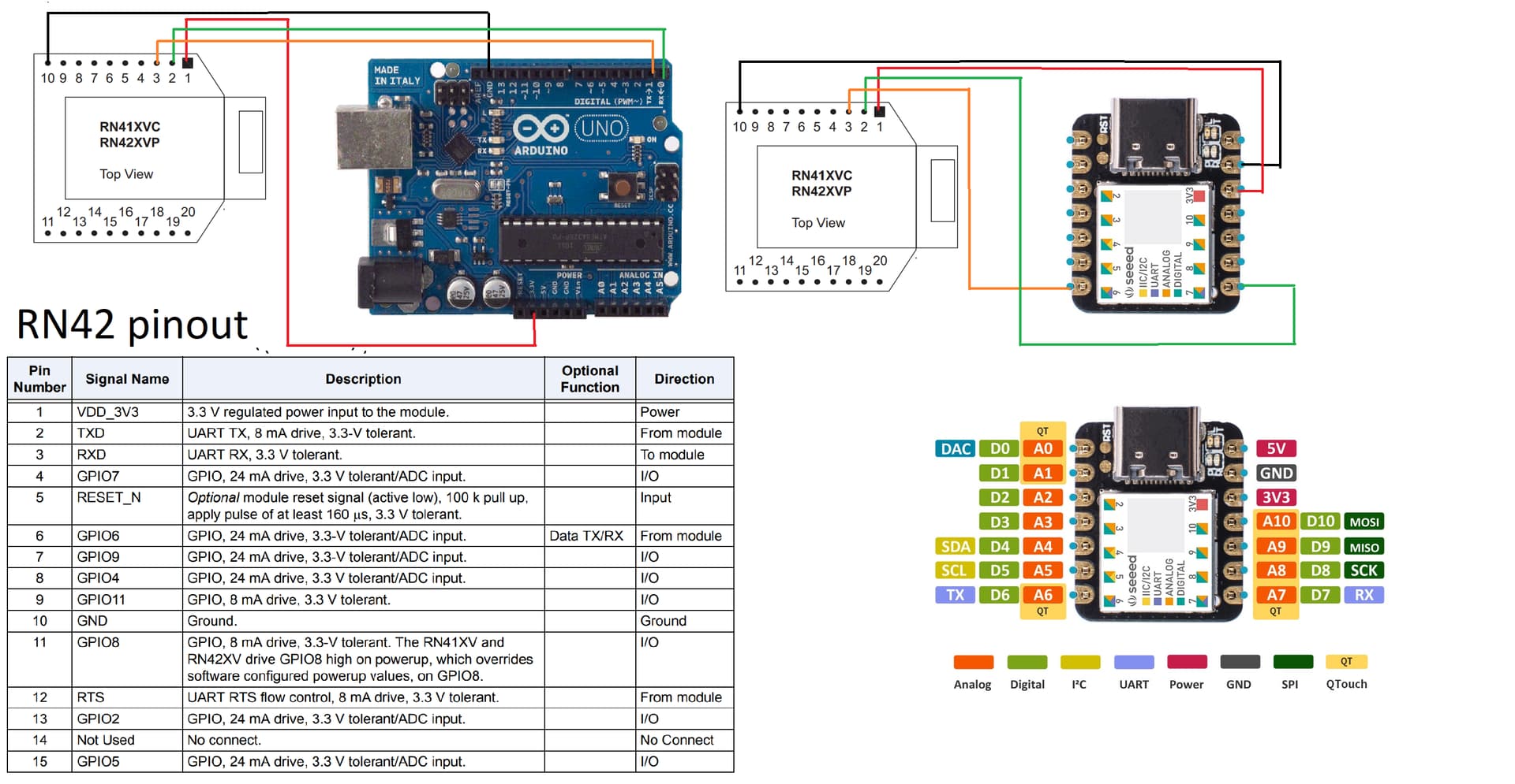
I simply connected the module to 3.3 V, GND, RX and TX of Arduino Uno board, I used the following options on CoolTerm and everthing worked.


I tried to repeat the same procedure on the Seeeduino, but when I type "A" or "B" on CoolTerm nothing happens.
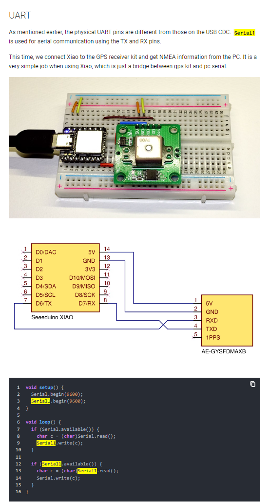
Someone told me that probably by connecting the Seeeduino with the USB- type C cable the port gets busy, so I tried using a software serial:

//REMEMBER AT FIRST YOU LOAD THE SKETCH WITHOUT TX AND RX THEN YOU CONNECT RX AND TX


#include <SoftwareSerial.h>

SoftwareSerial mySerial(9, 10); // RX, TX
void setup() {
  pinMode(6, OUTPUT);

  // set baudrate to match BT module:
  
  mySerial.begin(115200);
}
//void loop()
//{
//  if (mySerial.available())
//    Serial.write(mySerial.read());
//  if (Serial.available())
//    mySerial.write(Serial.read());
//}
void loop() {
  String t;// String to hold data from BT module:
  while(mySerial.available()){// keep reading bytes while they are still more in the buffer
    t+=(char)mySerial.read(); // read byte, convert to char, and append it to string
    }
   if(t.length()){ //if the string is not empty do the following

    if(t == "A\r\n"){ 
      mySerial.print("Brrrr! \n");
      digitalWrite(6, HIGH);
      delay(1000);
      digitalWrite(6, LOW);
    }
      else if(t == "B\r\n"){
        mySerial.print("Brr Brr\n");
        digitalWrite(6, HIGH);
        delay(500);
        digitalWrite(6, LOW);
        delay(500);
        digitalWrite(6, HIGH);
        delay(500);
        digitalWrite(6, LOW);
        }
      delay(1000);
    }
    //else{
     // Serial.print("Syntax Error\n");
     // }
    delay(20);
}

but nothing changes.
I also tried to avoid using the USB cable and I gave power to the Seeeduino through Arduino Uno by connecting the 5 V pins and GND with the first code I posted, but it still doesn't work.
What is the problem? Did I use the sofware serial correctly?

That looks bad to me. Never connect an UNO 5 volt output to the input of a 3.3 volt device without level conversion.

I don't know about Seeeduino....

Please post schematics explaining things. You write "I connected" and that is not clear enough.

1 Like

First of all thanks for your answer.
I will post the schematics as you requested, of course when I tried the software serial I connected the second and third pin of the RN42 to the seeeduino's 9 and 10 respectively.

That's not schematics. It's a tourist picture showing what the physical circuits look like. Helpers don't care where a connection is made on the physical circuit. What's interesting is what logic belongs to that pin.
Try again. Pen and paper, camera and posting.

I'll just post the Seeeduino connected to the RN42 since Arduino keeps working and doesn't represent a problem for me.
First picture: RN42 connected to Seeeduino's serial port made by pins 7 and 6: the red jumper goes from 3.3 V to VDD, the yellow jumper goes from Seeeduino's RX to RN42's TX, the blue jumper goes from Seeeduino's TX to RN42's RX and the grey one connects the two grounds.

Second picture: RN42 connected to Seeeduino's software serial port made by pins 10(TX) and 9(RX): the red jumper goes from 3.3 V to VDD, the yellow jumper goes from Seeeduino's 9 to RN42's TX, the blue jumper goes from Seeeduino's 10 to RN42's RX and the grey one connects the two grounds.

The third picture shows the connections to the module.
The module's led blinks when it is connected and then stays on when I enable the connection with CoolTerm.


I have made a little progress, with the following code:

#include <SoftwareSerial.h>

// Set up a new SoftwareSerial object with RX in digital pin 10 and TX in digital pin 11
SoftwareSerial portOne(0, 1);

void setup() {
    // Set the baud rate for the Serial port
    Serial.begin(115200);

    // Set the baud rate for the SerialSoftware object
    portOne.begin(115200);
}

void loop() {
//    if (portOne.isListening()) { 
//        Serial.println("portOne is listening!");
//        
//    }
    //char c = portOne.read();
    char s = portOne.peek();
   // Serial.println(c);
    Serial.println(s);
//     if (portOne.available()) { 
//        Serial.println("portOne is available!");
//        
//    }
}
    // ...

I was able to receive a character through the software serial port, as we can see on the serial monitor:

but this works only with the function peek, read doesn't work at all, the monitor remains blank.
With a previous test I've seen that

if (portOne.isListening()) { 
     Serial.println("portOne is listening!");

works as well, while

if (portOne.available()) { 
       Serial.println("portOne is available!");   
   }

doesn't work.

On Uno:
There is nothing wrong with your diagram in post #3. It is clear, comprehensive, and very well-presented. One problem that it shows with utmost clarity that no amount of pen, paper and camera will improve upon is that your RN42 is connected to Uno 3.3v. Class2 Blueteeth are not famous for their frugality and Uno is not famous for its largesse at 3.3v. I'm not familiar with the RN42, but you may simply be short of power, so, if you haven't already done so, check what is common practice with these devices.

Further, you have probably also been led astray on the matter of serial. It is quite OK to use hardware serial as you clearly show, and you clearly know the correct procedure, but using software serial at 115200 is a certain recipe for disaster. Either go back to what you had before, or change the software serial to 9600 - and reconfigure RN42 accordingly.....

Other than assuming its 3.3v is kosher for Bluetooth, I can't comment on that Seeeeeed thing but I would suggest that your diagram in post #3 is one hell of a lot more usable than the photos above and, next time you get monstered by the circuit-diagram nazis, just tell them to piss off.

The RN42 is not popular with Arduino users. The 3.3v power requirement may explain this.

I have heard rumour that the available current on the 3.3v pin varies with different Uno manufacturers. None of them are that great.

Your serial monitor output in post #6 is probably indicative of how bad an idea software serial is! The fact the you got something - anything - does hint that you have not damaged Bluetooth but a 1k/2k voltage divider in the Arduino Tx line would be a wise move. The same might apply to the Seeeed.
divider

1 Like

Hi @alessandro_capresi

One issue is that the Seeeduino XIAO doesn't have SoftwareSerial, instead it's possible to configure the SAMD21's microcontroller's spare Serial Communication (SERCOM) modules, to provide additional hardware Serial ports.

By default the XIAO by should offer Serial1 on digital pins D0 and D1.

Furthermore, the XIAO's limited pin count notwithstanding, there's the potential to configure additional SERCOM modules detailed in Adafruit's excellent tutorial here:

1 Like

@ MartinL
Gee, I thought the software serial was in the Uno code. I now understand that the Seeed is a little MCU in its own right and it speaks Arduino IDE(?)

On Uno:
There is nothing wrong with your diagram in post #3. It is clear, comprehensive, and very well-presented. One problem that it shows with utmost clarity that no amount of pen, paper and camera will improve upon is that your RN42 is connected to Uno 3.3v.

THANKS! I thought it was a very strange request.

Class2 Blueteeth are not famous for their frugality and Uno is not famous for its largesse at 3.3v. I'm not familiar with the RN42, but you may simply be short of power, so, if you haven't already done so, check what is common practice with these devices.

RN42 needs 3.3 V in input and it uses 3.3 V logic level:


it is a low power module afterall.

Further, you have probably also been led astray on the matter of serial. It is quite OK to use hardware serial as you clearly show, and you clearly know the correct procedure, but using software serial at 115200 is a certain recipe for disaster. Either go back to what you had before, or change the software serial to 9600 - and reconfigure RN42 accordingly.....
The RN42 comes with a 115200 baudrate, but I can set it to work with 9600. I can give it a try.

Other than assuming its 3.3v is kosher for Bluetooth, I can't comment on that Seeeeeed thing but I would suggest that your diagram in post #3 is one hell of a lot more usable than the photos above and, next time you get monstered by the circuit-diagram nazis, just tell them to piss off.

Thanks.

Your serial monitor output in post #6 is probably indicative of how bad an idea software serial is! The fact the you got something - anything - does hint that you have not damaged Bluetooth but a 1k/2k voltage divider in the Arduino Tx line would be a wise move. The same might apply to the Seeeed

It is a wise move for Arduino Uno because its uses 5V logic, but Seeeduino uses 3.3V

One issue is that the Seeeduino XIAO doesn't have SoftwareSerial, instead it's possible to configure the SAMD21's microcontroller's spare Serial Communication (SERCOM) modules, to provide additional hardware Serial ports.

Well this was something I started to think myself yesterday, trying to obtain another serial port is probably the solution to the problem.

Thanks for your advices and for giving me confirmations for the use of software serial with Seeeduino.

If I wanted to use this option, how should I modify my code? By just changing Serial to Serial1? I tried to do this but it doesn't work.

By reading this procedure found in Seeed Studio XIAO SAMD21 by Nanase - Seeed Wiki


Serial1 should be used with the pins enabled for RX and TX by default i.e. 7 and 8 and now it works!

This topic was automatically closed 180 days after the last reply. New replies are no longer allowed.