Hi everyone,
I'm hoping that I'm not going mad here, but with this temperature it's entirely possible.
tl;dr
Does micros() just count up?
I'm trying to do a simple program to drive a standard PC 4 pin PWM fan. I have the PWM side working correctly care of a lot of posts on here, my next trick is to get the RPM of the fan.
What I'm not understanding is the micros(). I thought that I could set a start and end time variable with micros() and calculate the time from that, however when I try I get odd results.
When I was debugging this I finding that micros jumped forwards and backwards (see output below). Is this expected behaviour or am I missing something? Oscillicope output gives an ok output from the RPM pin.
Output
15:24:22.648 -> Cycle=1
15:24:22.648 ->      Micros      :5000720
15:24:22.681 ->      Micros      :5001204
15:24:22.715 ->      Micros      :5001676
15:24:22.749 ->      Micros      :5002108 <- Out of sequence number
15:24:22.783 ->      Micros      :5001520
15:24:22.783 ->      Micros      :5001948
Code
// PWM Fan controller with RPM

const byte OC1A_PIN = 9;        //Fan PWM Pin
const byte OC1B_PIN = 10;
int RPMPin = 2;                 //Fan RPM Pin
unsigned long RPMSpeed;         //RPM Speed duration
unsigned long start_time;       //Start Time for RPM evaluation
unsigned long end_time;         //End Time for RPM evaluation
unsigned long delay_start;      //Start time for delay
unsigned long delay_end;        //End time for delay
const word PWM_FREQ_HZ = 25000; //Adjust this value to adjust the frequency, set to 25KHz
const word TCNT1_TOP = 16000000/(2*PWM_FREQ_HZ);

void setup() {

  Serial.begin(9600);
  pinMode(OC1A_PIN, OUTPUT);
  pinMode(RPMPin,INPUT_PULLUP);
  start_time = micros();
  end_time = start_time;
  RPMSpeed = 0;
  delay_start = millis();
  attachInterrupt(digitalPinToInterrupt(RPMPin), setRPM, CHANGE);

  // Clear Timer1 control and count registers
  TCCR1A = 0;
  TCCR1B = 0;
  TCNT1  = 0;
  TCCR1A |= (1 << COM1A1) | (1 << WGM11);
  TCCR1B |= (1 << WGM13) | (1 << CS10);
  ICR1 = TCNT1_TOP;
}

void loop() {
  for (int cycle = 0; cycle < 5; cycle++)
  {
    Serial.print("Cycle=");
    Serial.println(cycle);
    setPwmDuty(cycle*25);
    delay_start=millis();
    delay_end = delay_start + 5000;
    while (delay_start<delay_end)
      {
        delay_start=millis();
      }
    Serial.print("RPM=");
    Serial.println(RPMSpeed);
    Serial.println();
  }
}

void setPwmDuty(byte duty) {
  OCR1A = (word) (duty*TCNT1_TOP)/100;
}

void setRPM() {
  end_time = micros();
  Serial.print("     Micros      :");
  Serial.println(micros());
  if (end_time-start_time>0)
    {
      RPMSpeed  = (end_time - start_time);
    }
    else
    {
      RPMSpeed = 0;
    }
  start_time=end_time;
}
Thanks for any help and guidance you can provide.
Serial print should not be used in an ISR. Set a flag in the ISR, do the prints in loop() if the flag is set and clear the flag.
Variables used in an ISR should be declared volatile.
Multi byte variable that are changed in an ISR and read in loop() should be read while interrupts are disabled so that the variable cannot change while being read.
noInterrupts();
unsigned long copyVar = RPMSpeed;
interrupts();
Then print or work with copyVar.
groundFungus:
Variables used in an ISR should be declared volatile.
To be a little more specific about that, it applies only to variables that are shared between the ISR and the main program. You don't make all of them volatile. So, "global variables used in an ISR".
groundFungus and aarg, thank you for your guidance.
I've stopped the Serial.print from the ISR and declared the three variables (RPMSpeed, start_time and end_time) as volatile (though if I read it right as start_time and end_time are only used in the ISR I don't need to declare them as volatile).
I have also added three lines for noInterrupts, copy the RPMSpeed variable and then enable interrupts again.
Trouble is, the values that are coming back don't make sense.
Here's a quick copy of the output
	Run 1	Run 2	Run 3	Run 4
Cycle 0	12012	13164	13212	140
Cycle 1	40	28	20	16
Cycle 2	20	12	36	12
Cycle 3	28	12	40	40
Cycle 4	11096	11172	10392	11188
At the moment RPMSpeed should be counting the times between pulses on the hall effect sensor on the fan which I'm estimating to be around 3600 RPM. I know it's not RPM at the moment, but I would expect the values to be around:-
Cycle   RPMSpeed
0       0
1       33
2       16
3       11
4       8
Updated code is here. Any pointers as to where am I going wrong?
// PWM Fan controller with RPM

const byte OC1A_PIN = 9;             //Fan PWM Pin
const byte OC1B_PIN = 10;
int RPMPin = 2;                      //Fan RPM Pin
volatile unsigned long RPMSpeed;     //RPM Speed duration
volatile unsigned long start_time;   //Start Time for RPM evaluation
volatile unsigned long end_time;     //End Time for RPM evaluation
unsigned long delay_start;           //Start time for delay
unsigned long delay_end;             //End time for delay
const word PWM_FREQ_HZ = 25000;      //Adjust this value to adjust the frequency, set to 25KHz
const word TCNT1_TOP = 16000000/(2*PWM_FREQ_HZ);

void setup() {

  Serial.begin(9600);
  pinMode(OC1A_PIN, OUTPUT);
  pinMode(RPMPin,INPUT_PULLUP);
  start_time = micros();
  end_time = start_time;
  RPMSpeed = 0;
  delay_start = millis();
  attachInterrupt(digitalPinToInterrupt(RPMPin), setRPM, CHANGE);

  // Clear Timer1 control and count registers
  TCCR1A = 0;
  TCCR1B = 0;
  TCNT1  = 0;
  TCCR1A |= (1 << COM1A1) | (1 << WGM11);
  TCCR1B |= (1 << WGM13) | (1 << CS10);
  ICR1 = TCNT1_TOP;
}

void loop() {
  for (int cycle = 0; cycle < 5; cycle++)
  {
    Serial.print("Cycle=");
    Serial.println(cycle);
    setPwmDuty(cycle*25);

    delay_start=millis();
    delay_end = delay_start + 5000;
    while (delay_start<delay_end)
      {
        delay_start=millis();
      }
    noInterrupts();
    unsigned long locRPM=RPMSpeed;
    interrupts();
    Serial.print("RPM=");
    Serial.println(locRPM);
  }
}

void setPwmDuty(byte duty) {
  OCR1A = (word) (duty*TCNT1_TOP)/100;
}

void setRPM() {
  end_time = micros();
  if (end_time-start_time>0)
    {
      RPMSpeed  = (end_time - start_time);
    }
    else
    {
      RPMSpeed = 0;
    }
  start_time=end_time;
}
I really appreciate your help.
unsigned long locRPM=RPMSpeed; You take a copy, but you don't use it.
TheMemberFormerlyKnownAsAWOL ugh, sorry, good catch, missed that. I've corrected it (and edited the code in the message) and tried again but it's not solved the problem.
Hmm, I'm beginning to wonder if it's a hardware problem rather than a software one.
I've tried calculating the time between pulses a different way (without using an interrupt) and I'm getting random values all the time. I'm wondering if the trigger isn't enough to trigger the pin every time.
Here's the new code
// PWM Fan controller with RPM

const byte OC1A_PIN = 9;             //Fan PWM Pin
const byte OC1B_PIN = 10;
int RPMPin = 2;                      //Fan RPM Pin
byte Last_HES_Trigger;               //Last trigger pulse from Hall Effect Sensor
byte HES_Trigger;                     //Trigger pulse from the Hall Effect Sensor
unsigned long trigger_micros;        //End Time for RPM evaluation
unsigned long previous_trigger_micros; //Start time for RPM evaluation
unsigned long microsThisRev;         //Duration of turn
unsigned long delay_start;           //Start time for delay
unsigned long delay_end;             //End time for delay
const word PWM_FREQ_HZ = 25000;      //Adjust this value to adjust the frequency, set to 25KHz
const word TCNT1_TOP = 16000000/(2*PWM_FREQ_HZ);

void setup() {

  Serial.begin(9600);
  pinMode(OC1A_PIN, OUTPUT);
  pinMode(RPMPin,INPUT_PULLUP);
//  attachInterrupt(digitalPinToInterrupt(RPMPin), setRPM, CHANGE);

  // Clear Timer1 control and count registers
  TCCR1A = 0;
  TCCR1B = 0;
  TCNT1  = 0;
  TCCR1A |= (1 << COM1A1) | (1 << WGM11);
  TCCR1B |= (1 << WGM13) | (1 << CS10);
  ICR1 = TCNT1_TOP;
}

void loop() {
  for (int cycle = 0; cycle < 5; cycle++)
  {
    Serial.print("Cycle=");
    Serial.println(cycle);
    setPwmDuty(cycle*25);

    //Give it a second to stabilise the RPM
    delay_start=millis();
    delay_end = delay_start + 1000;
    while (delay_start<delay_end)
      {
        delay_start=millis();
      }
    //Let's run for 4 seconds, counting the RPM through that time
    delay_start=millis();
    delay_end = delay_start + 4000;
    while (delay_start<delay_end)
      {
        delay_start=millis();
        Last_HES_Trigger = HES_Trigger;                                  //What was the last sensor state
        HES_Trigger = digitalRead(RPMPin);                               //What is the current sensor state
        if (HES_Trigger == LOW && Last_HES_Trigger == HIGH)              //Has the sensor gone from HIGH to LOW
        {
          trigger_micros=millis();                                       //Get the current millis() (this_time)
          Serial.println(trigger_micros-previous_trigger_micros);
          microsThisRev=trigger_micros - previous_trigger_micros;        //Duration is this_time - last_time
          previous_trigger_micros = trigger_micros;                      //Set the last_time
        }
      }
    Serial.print("RPM=");
    Serial.println(microsThisRev);
    microsThisRev=0;                                                     //Set back to 0 RPM (in case the fan is stopped next time)
  }
}

void setPwmDuty(byte duty) {
  OCR1A = (word) (duty*TCNT1_TOP)/100;
}
And the output for a bit of the first cycle.
13:38:19.731 -> Cycle=0
13:38:24.741 -> RPM=0
13:38:24.741 -> Cycle=1
13:38:25.754 -> 6000
13:38:25.788 -> 45
13:38:25.788 -> 1
13:38:25.788 -> 14
13:38:25.821 -> 35
13:38:25.855 -> 19
13:38:25.855 -> 1
13:38:25.855 -> 13
13:38:25.923 -> 45
13:38:25.923 -> 1
13:38:25.923 -> 24
13:38:25.990 -> 68
13:38:26.057 -> 44
13:38:26.057 -> 1
13:38:26.057 -> 10
13:38:26.057 -> 1
13:38:26.057 -> 13
13:38:26.125 -> 49
13:38:26.125 -> 1
13:38:26.158 -> 19
13:38:26.192 -> 44
13:38:26.192 -> 1
13:38:26.192 -> 14
13:38:26.192 -> 1
13:38:26.226 -> 9
13:38:26.259 -> 55
13:38:26.293 -> 14
13:38:26.327 -> 63
13:38:26
attachInterrupt(digitalPinToInterrupt(RPMPin), setRPM, CHANGE);
Why interrupt on BOTH edges of the pulse? Typically to find the time between pulses you would pick the leading edge of the pulse, which may be a RISING edge or FALLING edge. The time between the leading and trailing edges has nothing to do with the time between pulses.
johnwasser, it's a fair question, it's probably where I'd left the code after trying all the other options (RISING, FALLING, LOW and HIGH). Regardless of the mode what's coming back is neither consistent, realistic or valid.
Where are the pulses coming from. Maybe now is a good time to post a schematic and data sheet of the fan.
 delay_start=millis();
    delay_end = delay_start + 1000;
    while (delay_start<delay_end)
      {
        delay_start=millis();
      }
How is that different than just using delay()?
turbine_2:
johnwasser, it's a fair question, it's probably where I'd left the code after trying all the other options (RISING, FALLING, LOW and HIGH). Regardless of the mode what's coming back is neither consistent, realistic or valid
Here is how to do that:
- copy the line you want to experiment with
- paste it just below, on the following line
- comment out one of them with //
- edit the other line
Then when you realize you got nowhere with your changes,
- delete the experimental line
- remove the // from the original line
groundFungus:
delay_start=millis();
delay_end = delay_start + 1000;
while (delay_start<delay_end)
{
delay_start=millis();
}
How is that different than just using delay()?
It fails when millis() rolls over. 
aarg:
So, "global variables used in an ISR".
No, NOT only "global" variables! ANY variables that are accessed BOTH in both foreground and background code! They do not need to be global.
Regards,
Ray L.
RayLivingston:
No, NOT only "global" variables! ANY variables that are accessed BOTH in both foreground and background code! They do not need to be global.
Regards,
Ray L.
Would they not at least need to be static? My thought, and of course I have been wrong many times before, is that the compiler would need to have a fixed address for any variable that is shared that way. Otherwise, how would the ISR code know the location of the variable? If it were a local variable, the address would not be known at compile time.
Also what about scope? How would you reference a variable declared inside a function, from an ISR?
I suggest trying an VERY simple frequency meter sketch to see if your random results are coming from a noisy input or bad math in your sketch. If you can't get good data from your input it is going to be nearly impossible to get good outputs no matter how much you filter.
Here is a sketch I just wrote to test counting pulses per second on Pin 2. I use a servo output on Pin 3 as a test input since I know servo pulses are at 50 Hz. I use a single-byte variable for the counter since that doesn't require local buffering. It is reporting the expected 50 pulses every second. Does it report the expected 60 pulses from your 3600 RPM (60 RPS) input?
#include <Servo.h>

const byte RPMPin = 2;                 //Fan RPM Pin

volatile byte Pulses;


// Using a servo output as a test input.  Pulses repeat at 50 Hz.

Servo servo;


void setup()

{

  Serial.begin(115200);

  pinMode(RPMPin, INPUT_PULLUP);

  servo.attach(3);

  attachInterrupt(digitalPinToInterrupt(RPMPin), countPulses, FALLING);

}


void countPulses()

{

  Pulses++;

}


void loop()

{

  Serial.println(Pulses);

  Pulses = 0;

  delay(1000);

}
groundFungus:
Where are the pulses coming from. Maybe now is a good time to post a schematic and data sheet of the fan.
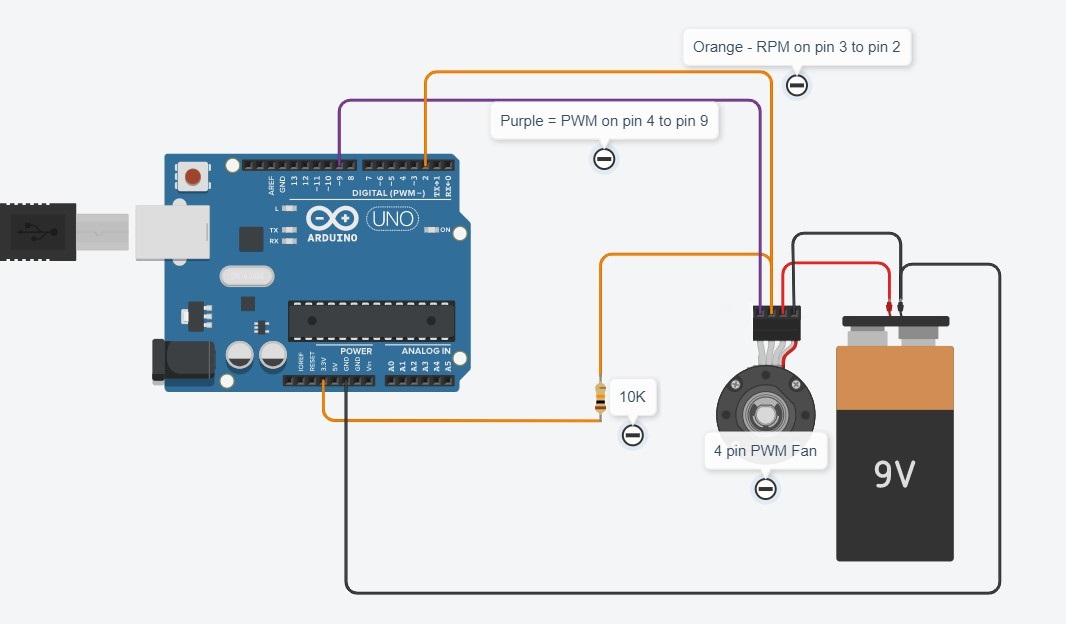
The pulses are coming from the hall effect sensor on the 4 pin fan. It's a standard PC 4 pin fan (Coolmaster DC1202512RFUN). Here's my circuit (not great at tinkercad for circuits I'm afraid).
groundFungus:
How is that different than just using delay()?
Um, the examples I've looked at used this so I've just followed them.
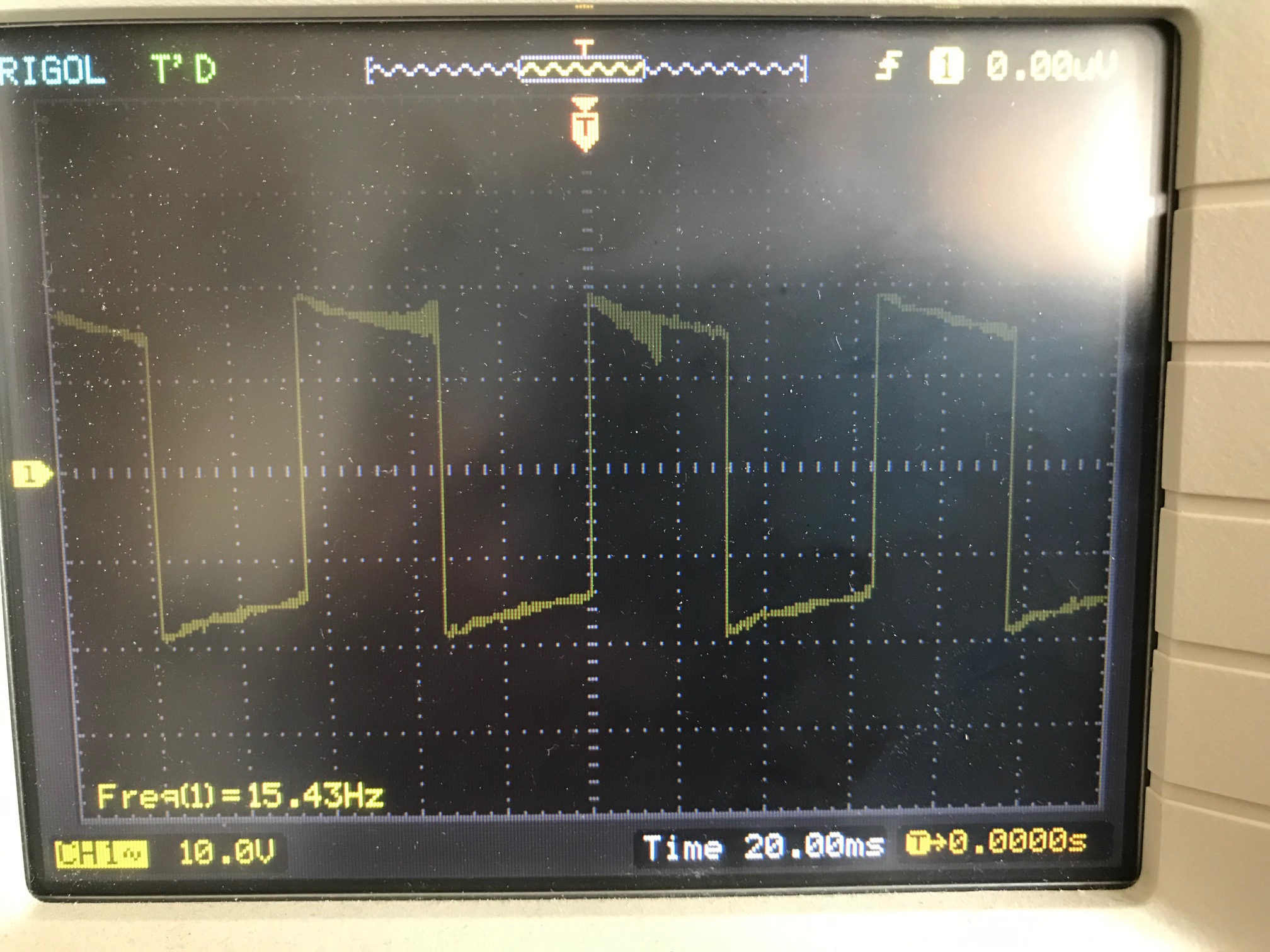
Here's the output I'm getting on my scope for one of the cycles.
johnwasser, I'll give that a go, thanks.
Is the power supply really.a 9V smoke alarm battery? If not, what are the specs of the supply (Volts, Amps)? Why is the pull-up on pin 2 to 3.3V, not 5V? Why not use the internal pullup on pin 2?
I am having a hard time finding info on the fan. Can you post a link to a data sheet or manual?
What is the amplitude of the pulses on the scope photo?
johnwasser:
Here is a sketch I just wrote to test counting pulses per second on Pin 2. I use a servo output on Pin 3 as a test input since I know servo pulses are at 50 Hz. I use a single-byte variable for the counter since that doesn't require local buffering. It is reporting the expected 50 pulses every second.
Yes, when I run this sketch I get 50 back every time.
groundFungus:
Is the power supply really.a 9V smoke alarm battery? If not, what are the specs of the supply (Volts, Amps)? Why is the pull-up on pin 2 to 3.3V, not 5V? Why not use the internal pullup on pin 2?
I am having a hard time finding info on the fan. Can you post a link to a data sheet or manual?
What is the amplitude of the pulses on the scope photo?
Yes, (for now) the supply is a 9V smoke alarm battery 6LR61. I will use a 12V supply when I get this all working.
The pull up is on the 3.3v supply because that's what the diagram used (one link is here but there are others that all point to the same). I've also stuck the resistor in there as that's what the other diagrams do (although resistance values vary).
I don't have a datasheet, but have been assuming that the fans follow the standard here
I've just put the pin in 5v rather than 3.3v and the output on my current non-interrupt code is looking a lot better (69, 36, 27 and 21 +-1 consistently), so that's a good step forward thank you. I'll try working with the interrupt version now.
I really appreciate all of your help on this.