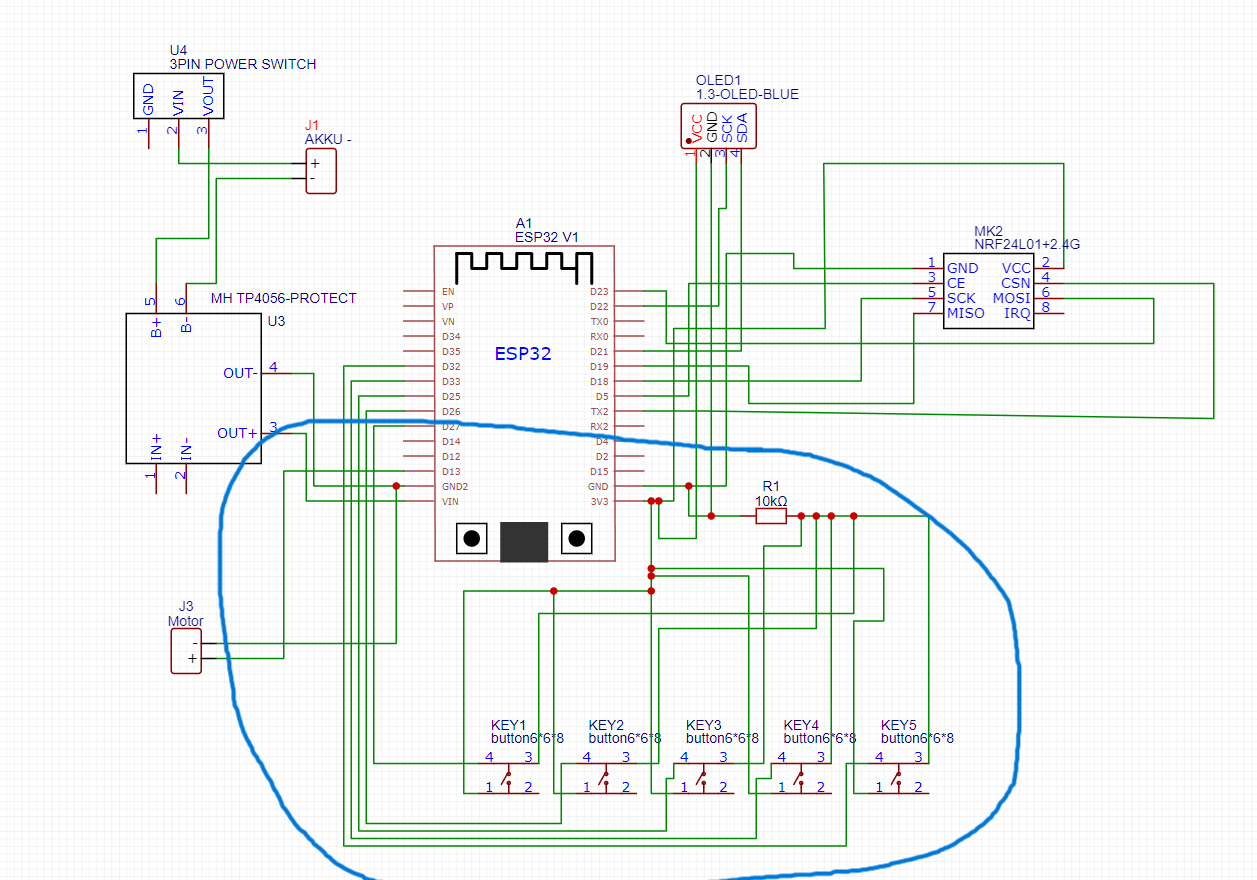
Hi I have a big problem with my circuit which includes 5 push buttons, an ESP32 and a 10K ohm resistor. Each of the 5 buttons is connected to the same Vcc and a 10K resistor, but with 5 different pins on the ESP. You could also see this wiring on the attached picture. It's about the 5 switches at the bottom. The problem is that I can't read the switches individually (i.e. pin for pin) and all pins are always triggered as soon as a switch is pressed. Maybe I'm just blind and don't see the error, so I'd really appreciate an answer!! ![]()
You need a separate resistor for each push button.
1 Like
As pointed out, you would need a resistor per pin/button, and even then the circuit would not work because when the buttons are not pressed, the pins are floating.
But actually you don't need a resistor at all. Simply connect each button between the ESP pin and ground, and set the mode of each pin to INPUT_PULLUP.
Thank you so much for your quick reply! ![]() I already thought that it could be because of this, but first of all I can't think of any technical reason for this and other projects such as the hack hero Vega from Spacehuhn only use a resistor (see picture). How is that possible then?
I already thought that it could be because of this, but first of all I can't think of any technical reason for this and other projects such as the hack hero Vega from Spacehuhn only use a resistor (see picture). How is that possible then? ![]()
Essentially all you buttons are in parallel, pushing one pushes them all.
How is that possible then?
Show me the schematic, telI me what it does and I will tell you how
2 Likes
Unfortunately, there is no wiring diagram online, but the switches should actually be connected exactly like this. Is it the Basically possible to operate the switches with one resistor?
It's possible to operate them with NO resistor.
Connect one end of each switch to ground and the other end to an ESP pin.
Set the ESP pin to inputpullup. When the switch is pushed the input will go from HIGH to LOW
1 Like
It is basically possible to operate the switches without any external resistors is you use the internal resistors.
Thank you for your answer! I'm using an already pre-made code that I unfortunately can't change (so I can't change the mode to INPUT_PULLUP). What exactly do you mean by floating?
Then you need to use separate resistors.
1 Like
Why, have you got the code on file?
Is this a kit you have purchased?
If so can you please post a link to where you got it.
Post a link to where you got the Hackhelo VegaII pcb?
Thanks.. Tom... ![]()
![]()
![]()
![]()
Hi,
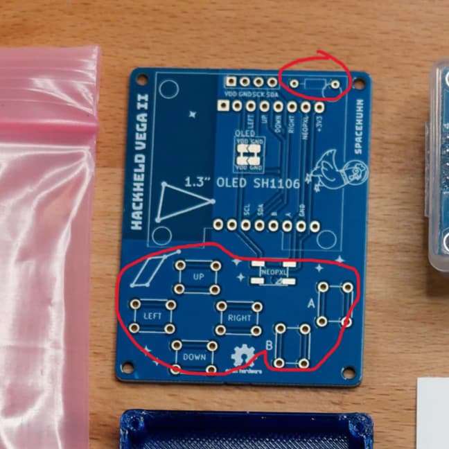
I think thisd is your project.
Did you reverse engineer the PCB to see if that is how the buttons are connected?
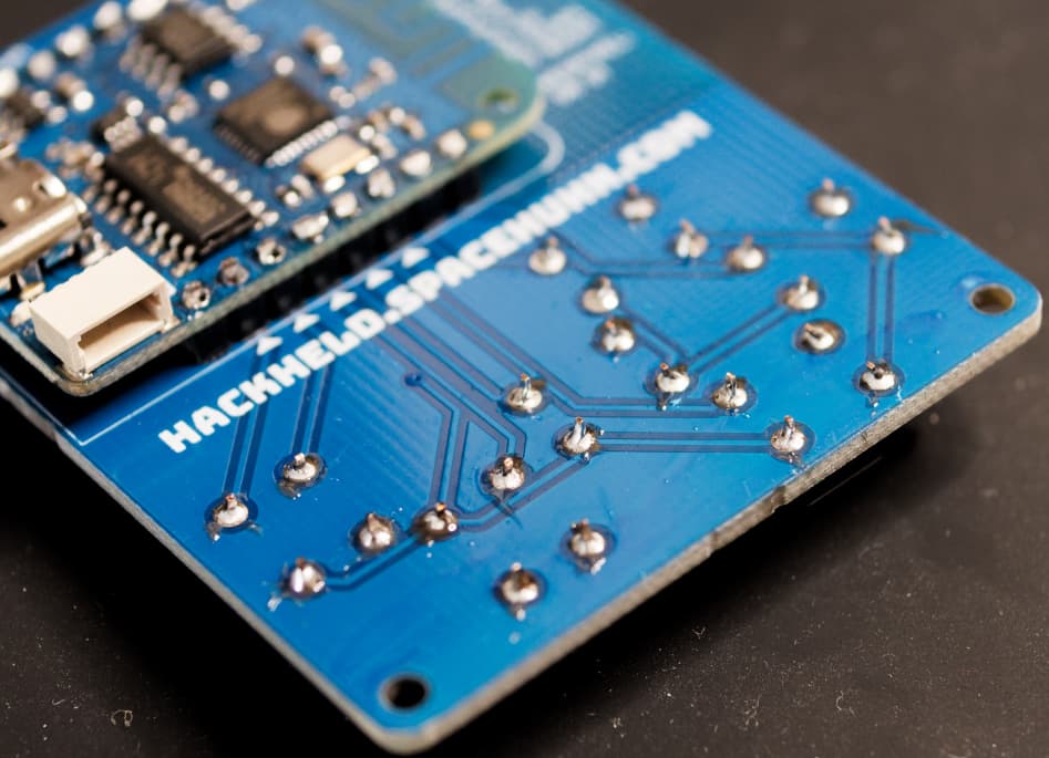
Back of PCB;
Front of PCB;

Tom.. ![]()
![]()
![]()
![]()
1 Like
Seems to me that you can't change the code and you can't change the circuit. If it doesn't work...
Maybe. ESP32 pins have INPUT_PULLDOWN mode. If that mode is used, you could use a low value resistor, or even just a wire link where the resistor would be on your PCB.
Hi, @nobudget
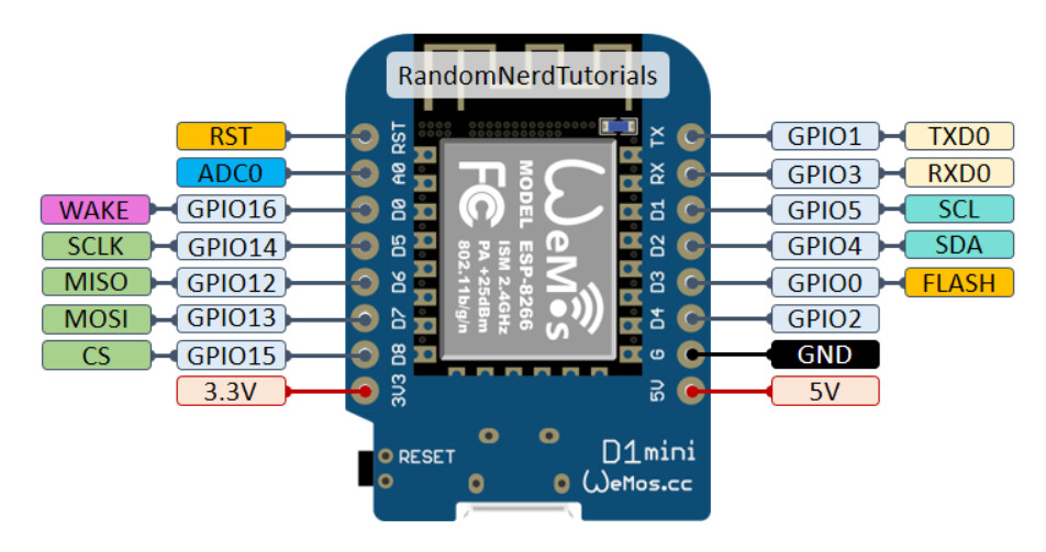
Your project uses a D1 Mini, so your circuit is not correct for a start.
As you show an ESP32.

Re do your circuit diagram.
Just draw the button circuit, with a pen(cil) and paper.
I can see from the site they provide a .bin code not the Arduino IDE code.
Have you successfully loaded the code?
Does the display show anything?
So how do you know the buttons aren't working?
Do you have a DMM? (Digital MultiMeter)
Thanks.. Tom.... ![]()
![]()
![]()
![]()
Thanks to everyone for answering me so quickly and helpfully! I designed my own circuit board and oriented myself for the switch circuit on that of the Hackheld Vega. The code I want to use is therefore not for the Hackheld Vega at all, but a file that you have to flash to the Esp with a tool from Espressif. I'm sorry if this sounds confusing, but I hope it's still understandable. In addition to my own project (where the buttons don't work), I have such a hackheld Vega at home and it works without any problems, even though it only uses one resistor for 5 buttons. So I thought I could just copy the design. Thank you again for your great helpfulness and effort! ![]()
NoBudget
Hi,
Where did that come from, as you are using an ESP32, D1 is ESP8266?
What format is the flash code in?
Are you sure your code has flashed properly?
Your circuit of the buttons looks nothing like the Vega PCB pattern.
Can you please post some images of your PCB pattern?
Did you protoboard your project before going to PCB?
Can you please tell us your electronics, programming, arduino, hardware experience?
Thanks.. Tom.. ![]()
![]()
![]()
![]()
It's likely that you’re seeing cross-talk between the pins, especially if they’re wired together without proper isolation.
What I’d suggest is using pull-down resistors (individual for each pin) or enabling the internal pull-up resistors on the ESP32 for each button pin. That way, each button press will be isolated, and you can read the state of each pin independently.
Floating is when an input has nothing connected to it, either internal or external. As the input impedance of an unconnected input is very high, it can pick up external electric magnetic fields, from your local environment. Things like the mains electricity. This travels through the air like a radio.
The problem with a floating input is that when you read it, then it can return any value. Either high or low for a digital read, or any value between 0 and the maximum output of the analogue to digital converter in the case of reading through an analogue input.
So floating inputs are a bad thing and are to be avoided for any circuit.
Yes they have both pull-up and pull-down resistors. Both a weak at approximately 47K.
Note you have to search the data sheet for "pull-down" as "pulldown" will not find anything.
Hi, @nobudget
This is how the Hackheld PCB is wired.
From here;
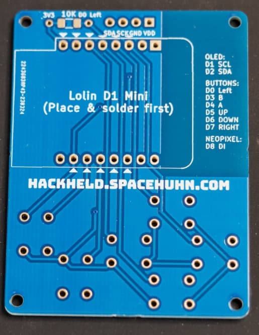
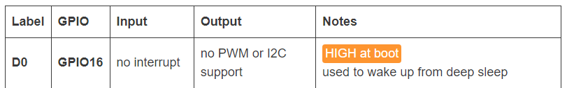
The 10K is a pullup for ONE of the buttons, I don't know why, it may be to do with the topography of the ESP8266.
The PCB overlay tells you that one end of the 10K is connected to 3V3 and the other if you follow the trace goes to ONE pin and ONE button.
So where did you get your button circuit?
Tom.. ![]()
![]()
![]()
![]()
![]()
![]()
![]()
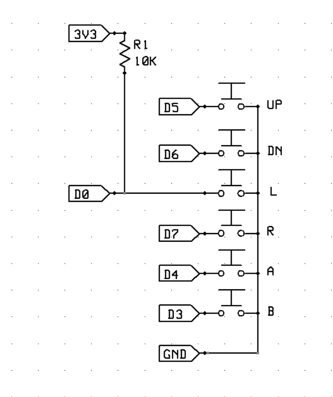
AFAIK R1 in the schematic you've shown is superfluous.
Yes, it's understandable.
You're using a binary file (so compiled code) which you can't modify.
You've made your own DIY PCB, but you don't know the code (it's already compiled after all) and you don't understand the basics of how GPIO inputs work.
The result is that you've painted yourself into a corner.
My advice would be to use the PCB that is intended to be used with the code/binary file you're using, so that you're 100% certain the combination will work.
1 Like