
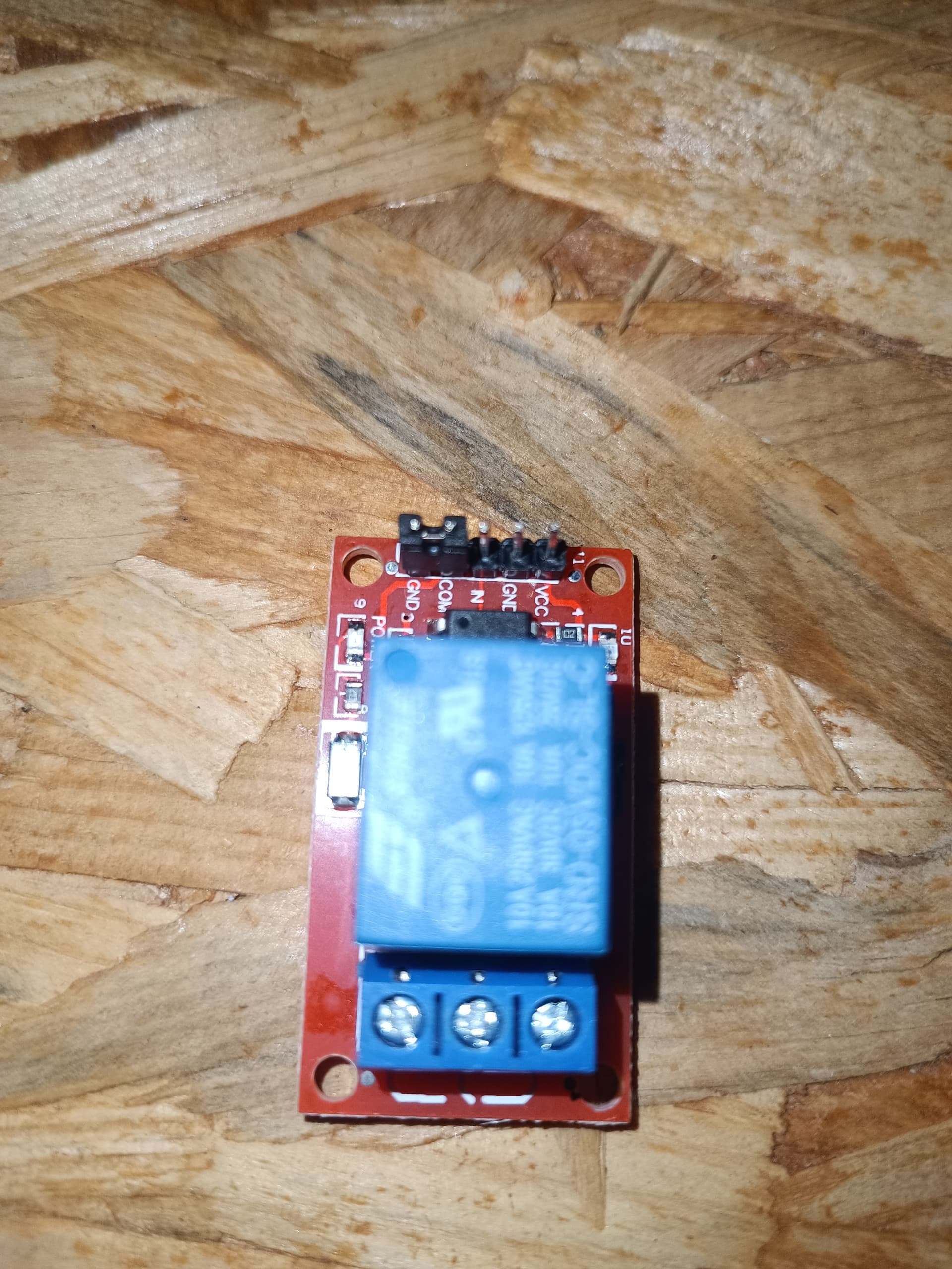
- That relay is different than the link you gave us.
1 Like
Yes, I couldn't check the exact relay type yesterday. I remembered incorrectly. I am sorry. I have realised my error just now when user 2112 notified me about jumper.
-
Okay, we need to try some experimenting.
-
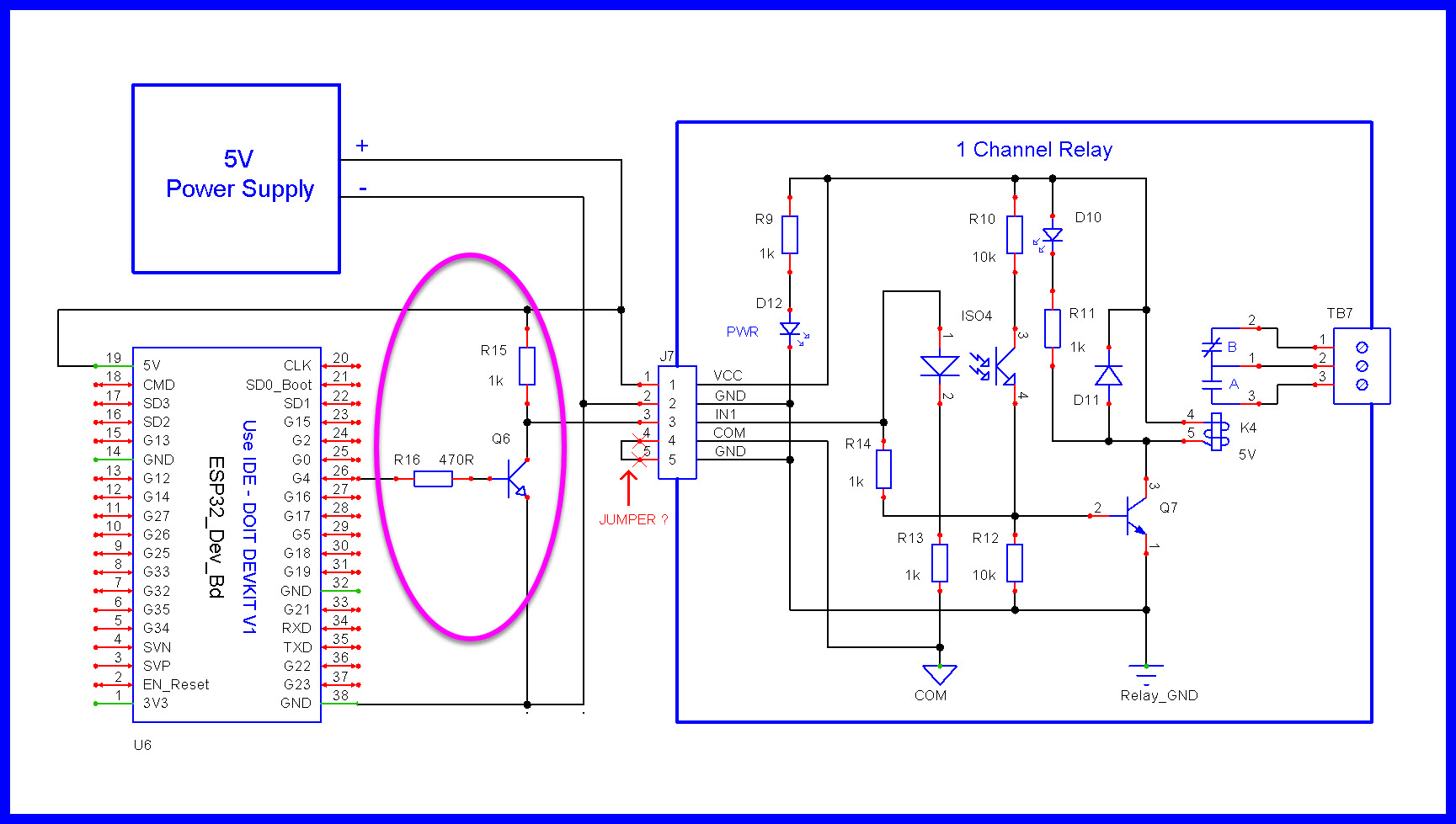
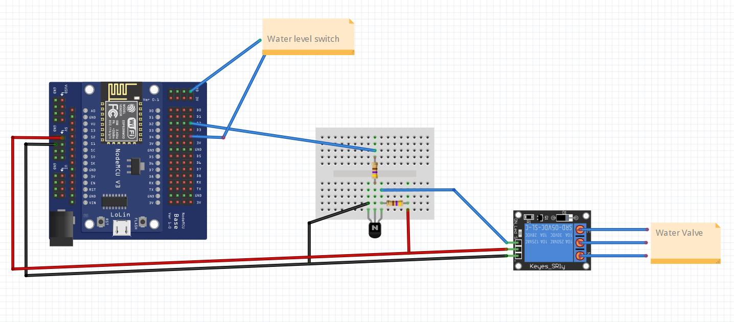
Add the 1k R15 resistor to your external transistor as seen in this image.
1 Like
Hmmm. If that jumper makes the relay trigger HIGH, where would you place it for trigger LOW?
We await your reverse engineered schematic. ![]()
![]()
More 3 for $2 undocumented AliExpress treasure?
1 Like


Now...when I connect nodemcu to power supply valve opens immediately and when I disconnect nodemcu, valve closes immediately... that's it... nothing else happens...ON/OFF button in BlynkIot doesn't work
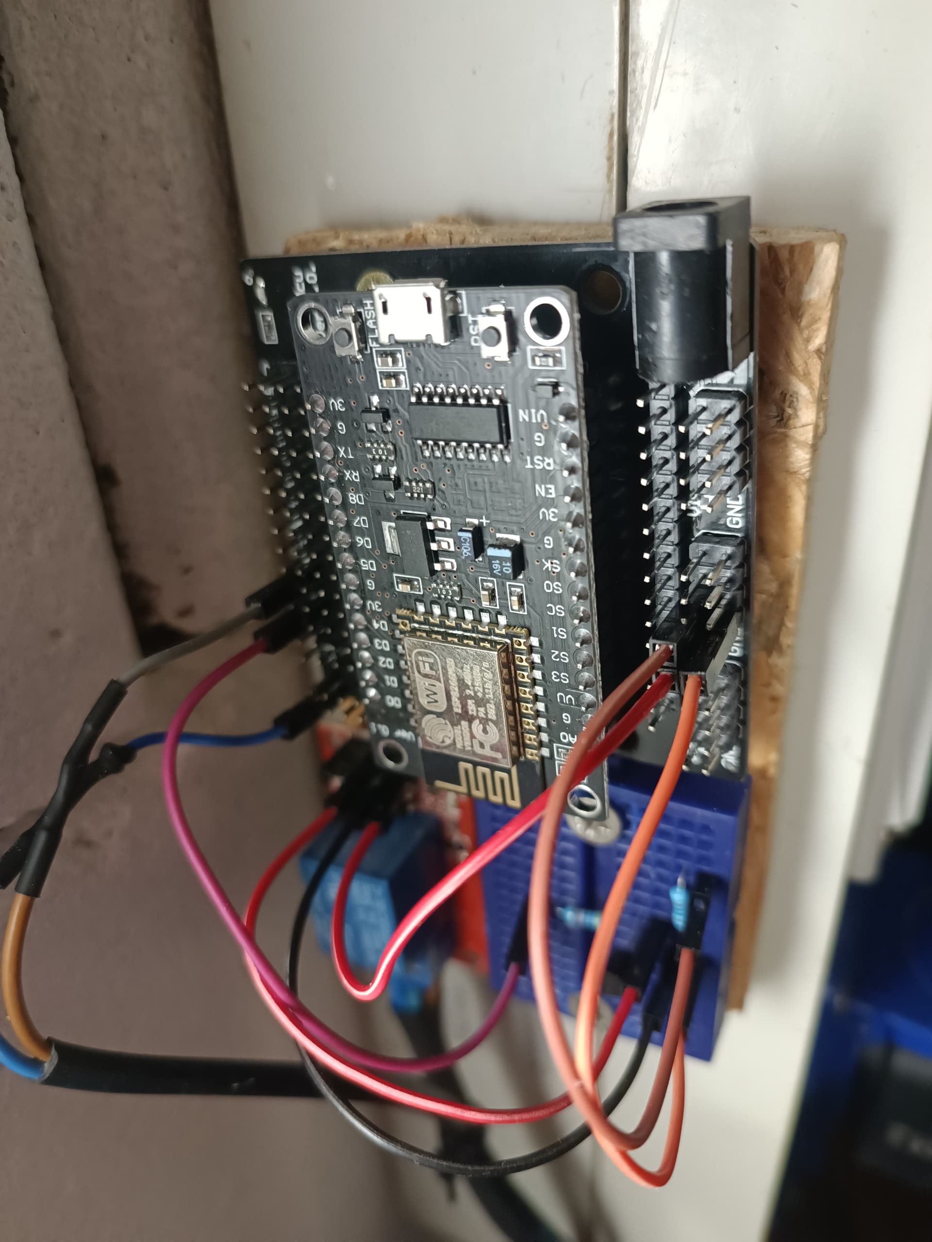
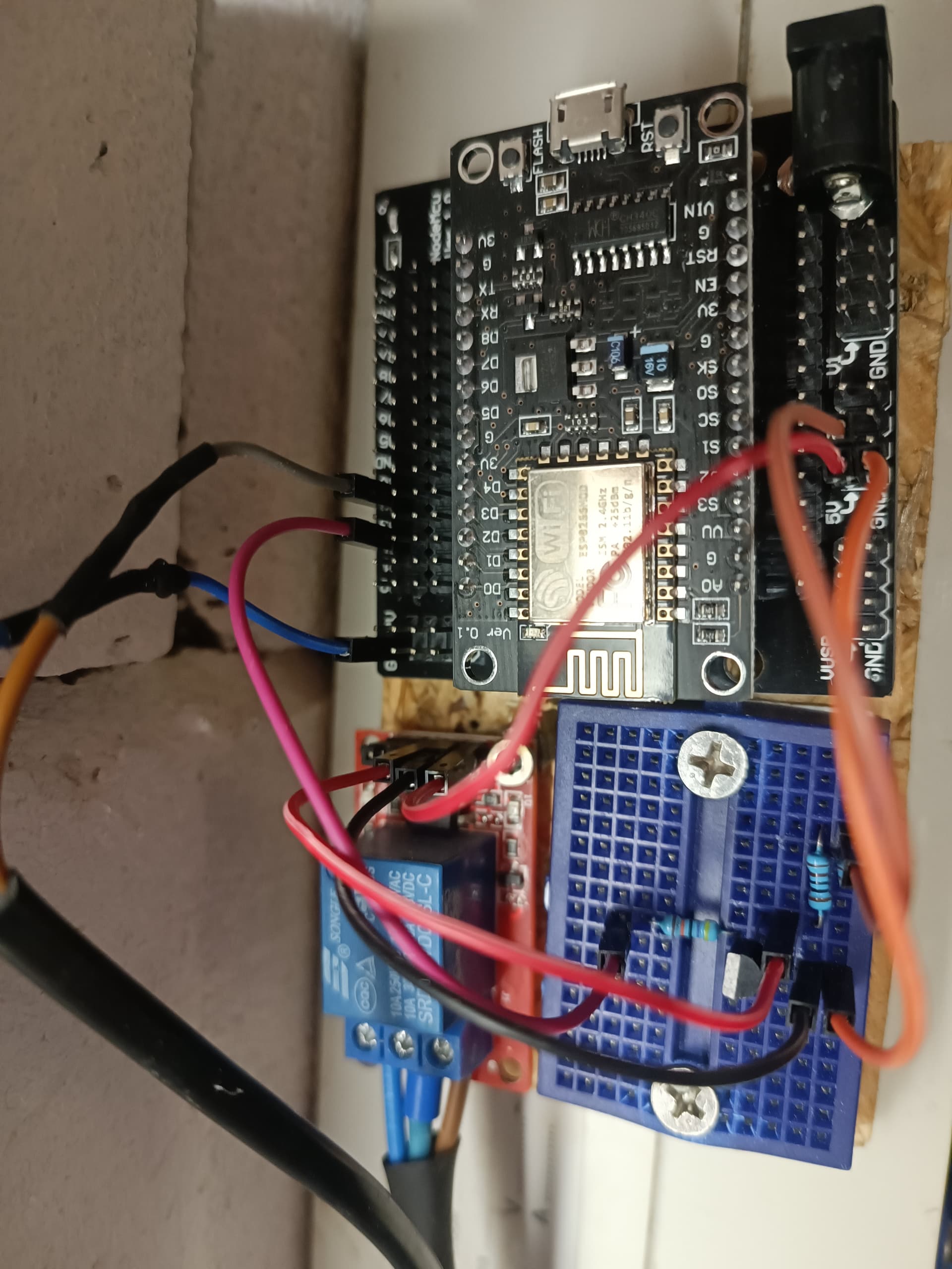
It is almost impossible to make better pictures ![]() Not easily accessible
Not easily accessible
-
Very difficult to see from the images if things are wired correctly.
-
Let’s assume things are wired properly as per the schematic.
-
When we add the external transistor, the output of the controller is inverted.
-
If you are observing the relay is operating opposite to your needs, then what you write to the controller relay output pin needs to be reversed.
-
With the external transistor, you need to digitalWrite a LOW to energize the relay,
digitalWrite a HIGH to de-energize the relay. -
Show us your current code.
-
Please confirm with an ohmmeter the 470 ohms and 1k transistor resistors are correct.
1 Like
My code is exactly the same like I posted in my first post. I didn't make any changes.
Now I am observing that the relay is not operating like I want at all.
I have a question about your schematic. What do you mean by "Jumper ?". I have to pull it out from the relay? Or what?
I will confirm ohms tomorrow...Whole thing is 50 kilometres from my apartment and I want to bring it with me tomorrow. I want to test it in simulated environment where I can take better pictures of wiring.
-
From what information I can see on your relay link, the jumper is not going to be an issue, however, it is very easy to test things with, then without the jumper installed, try both options yourself.
-
Referring to the schematic from post #28, I made some minor changes to your sketch in post #1, please try the changes below to see what happens.
#define BLYNK_TEMPLATE_ID ""
#define BLYNK_TEMPLATE_NAME ""
#define BLYNK_AUTH_TOKEN ""   //blynk token

#define BLYNK_PRINT Serial                                    //blynk
#include <ESP8266WiFi.h>
#include <BlynkSimpleEsp8266.h>

#define  pinZAPVYP D2                         //rele PIN

char auth[] = BLYNK_AUTH_TOKEN;               //blynk token
char ssid[] = "";
char password[] = "";

int FloatSensor = 2;                          //D4 pin of NodeMCU
int buttonState ;                             //reads pushbutton status

int statBUTTON=0;                             //relay

void setup() {
  Blynk.begin(auth, ssid, password);
  pinMode(FloatSensor, INPUT_PULLUP);

  pinMode(pinZAPVYP, OUTPUT);                 //relay
  digitalWrite(pinZAPVYP, HIGH);      // <——-<<<<  Relay de-energized

  Blynk.virtualWrite(V2, 0);
  delay(1000);
}

void loop() {

  Blynk.run();

  delay(1000);

  buttonState = digitalRead(FloatSensor);     // read the value of float sensor
  if (buttonState == HIGH)                    // if the value is HIGH
  {                                           // the level is high
  Blynk.virtualWrite(V3, 0);
  }
  else
  {
  Blynk.virtualWrite(V3, 255);
  }

  if(statBUTTON == 1)                          //rele
  {
  digitalWrite(pinZAPVYP, LOW);      // <——-<<<<  Relay energized
  }

  else
    {
        digitalWrite(pinZAPVYP, HIGH);       // <——-<<<<  Relay de-energized
    }

}

BLYNK_WRITE(V2)
{
  statBUTTON = param.asInt();
}
1 Like
I checked resistors - OK (470 and 1000)
I changed the code according to your instructions...and it looks fine...working with jumper!
But we will see how long ![]()
Thank you very much! You are the best!
final code:
#define BLYNK_TEMPLATE_ID ""
#define BLYNK_TEMPLATE_NAME ""
#define BLYNK_AUTH_TOKEN ""   //blynk token

#define BLYNK_PRINT Serial                                    //blynk
#include <ESP8266WiFi.h>
#include <BlynkSimpleEsp8266.h>

#define pinZAPVYP D2                         //relay PIN

#define relayOn    HIGH
#define relayOff   LOW

#define floatSensorOn    HIGH
#define floatSensorOff   LOW

char auth[] = BLYNK_AUTH_TOKEN;               //blynk token
char ssid[] = "";
char password[] = "";

int FloatSensor = 2;                          //D4 pin of NodeMCU
int buttonState ;                             //reads pushbutton status

int statBUTTON=0;                             //relay

void setup() {
  Blynk.begin(auth, ssid, password);

  pinMode(FloatSensor, INPUT_PULLUP);        //float sensor

  pinMode(pinZAPVYP, OUTPUT);                 //relay
  digitalWrite(pinZAPVYP, relayOff);          // <——-<<<<  Relay de-energized

  Blynk.virtualWrite(V2, 0);
  delay(1000);
}

void loop() {

  Blynk.run();

  delay(1000);

  buttonState = digitalRead(FloatSensor);     // read the value of float sensor
  if (buttonState == floatSensorOn)           // if the value is HIGH
  {                                           // the level is high
  Blynk.virtualWrite(V3, 0);
  }
  else
  {
  Blynk.virtualWrite(V3, 255);
  }

  if(statBUTTON == 1)                          //rele
  {
  digitalWrite(pinZAPVYP, relayOff);           // <——-<<<<  Relay energized
  }

  else
    {
        digitalWrite(pinZAPVYP, relayOn);      // <——-<<<<  Relay de-energized
    }

}

BLYNK_WRITE(V2)
{
  statBUTTON = param.asInt();
}
final schematic with NPN BC547 transistor:
1 Like
-
I am unable to run your sketch as I don’t have an ESP8266 nodemcu.
Not sure about your library operation.
If others can test the sketch please help out.
Still a possibility of problems may be in the code. -
Please confirm the water level sensor is a dry contact (no voltage).
Oh, same problem today. Relay doesn't work...no clicking sound. Water level sensor works ok.
-
The relay should be getting appropriate control voltage.
-There is a possibility the water valve being operated is feeding back EMI to the controller.
-There is a possibility other external electrical devices nearby are creating EMI.
-Make sure your water valve wiring is moved away from controller wiring. -
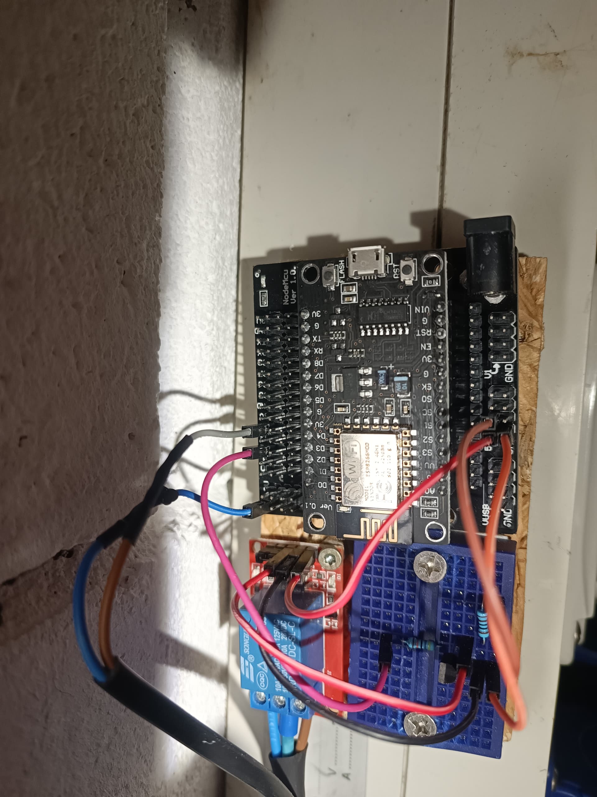
Show us an image of the areas surrounding the controller so we can see what other things are nearby.
-
If you had a new controller you could try that.
-
Some software gurus might be able to look at your code.
-
Maybe do some closer looking at your sketch to confirm data types aren’t being abused and look closer at things that can overflow.
-
Please confirm the water level sensor is a dry contact (no voltage).
-
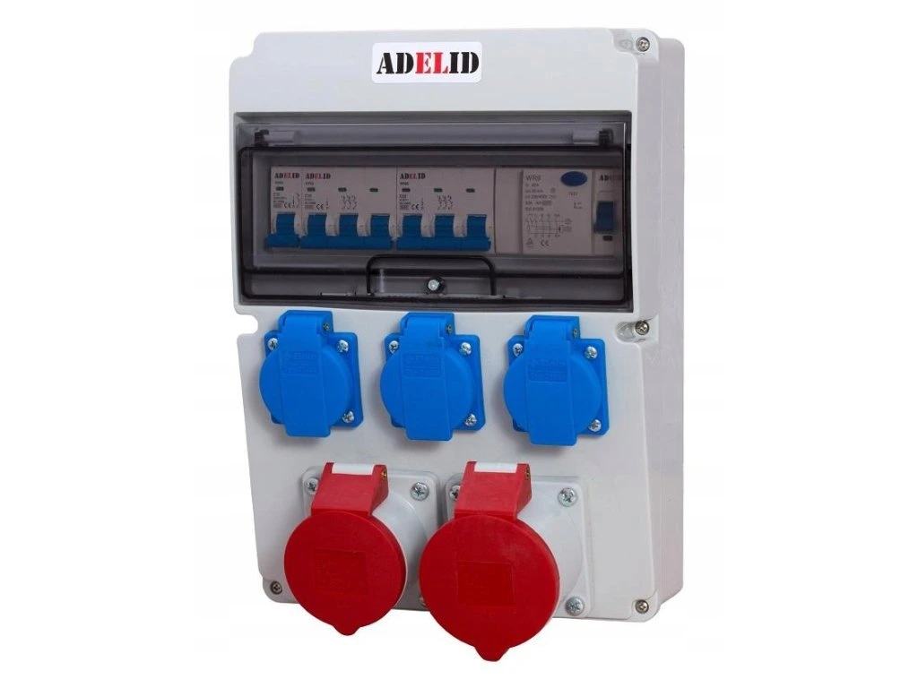
whole device is attached to the side of this box (I dont know the corect english name for it):
...maybe some EMI can occure (I am testing whole device at home now away from other electric devices) because into the box are connected several electric devices, one of them is close to my device 0,5 meter (water pump), but it has been switched off for two days:
...there are also 3 smart plugs connected to the box
...I am sure that water valve wiring is nowhere near the controler wiring -
I had also tested another new controler
-
I dont know what more I can do with my sketch

-
As far as I know the level sensor is a dry contact


Yesterday I disconnected the water valve and today the relay isn't working again. Therefore I consider the water valve not a plausible cause of EMI.
This topic was automatically closed 180 days after the last reply. New replies are no longer allowed.