Problem with 5V relay and nodemcu

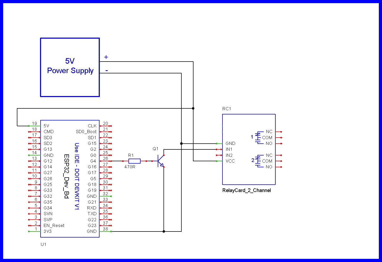
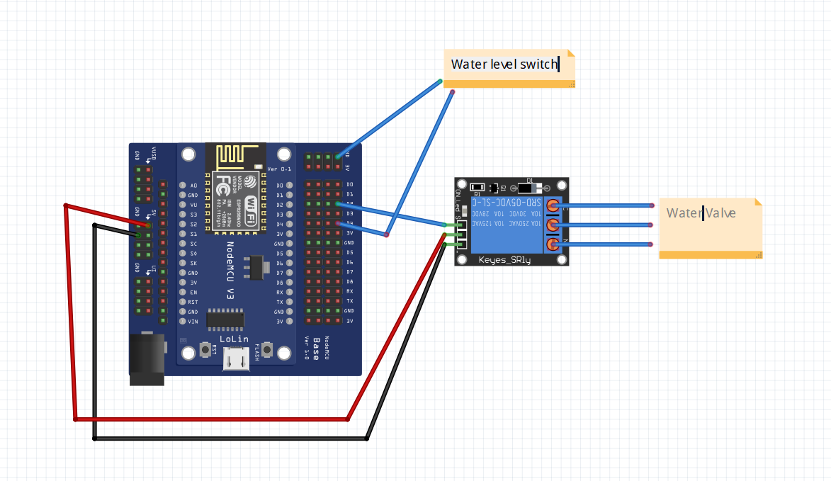
I am using ESP8266 nodemcu with MCU Base. There is a 1 Channel 5V Relay Module With Optocoupler SRD-5VDC connected to GPIO4. There is also Liquid Water Level Sensor conected to GPIO2.
When the water in the tank raises, the level sensor send a signal to GPIO2. Then the water valve conected to relay switches to open.
The problem is that everything is working fine from the beginning, but after few hours the relay always stops working - there is no clicking sound coming from the relay but I have checked that the water level sensor works fine - the activity shows on a SuperChart in BlynkIot. Then when I restart nodemcu everything again works fine. Then the relay stops working again after few hours.

code:

#define BLYNK_TEMPLATE_ID ""
#define BLYNK_TEMPLATE_NAME ""
#define BLYNK_AUTH_TOKEN ""   //blynk token

#define BLYNK_PRINT Serial                                    //blynk
#include <ESP8266WiFi.h>
#include <BlynkSimpleEsp8266.h>

#define  pinZAPVYP D2                         //rele PIN

char auth[] = BLYNK_AUTH_TOKEN;               //blynk token
char ssid[] = "";                         
char password[] = ""; 

int FloatSensor = 2;                          //D4 pin of NodeMCU
int buttonState ;                             //reads pushbutton status

int statBUTTON=0;                             //relay

void setup() {
  Blynk.begin(auth, ssid, password); 
  pinMode(FloatSensor, INPUT_PULLUP);         
  pinMode(pinZAPVYP, OUTPUT);                 //relay
  digitalWrite(pinZAPVYP, LOW);
  Blynk.virtualWrite(V2, 0);
  delay(1000);
}

void loop() {

  Blynk.run(); 

  delay(1000);
  
  buttonState = digitalRead(FloatSensor);     // read the value of float sensor
  if (buttonState == HIGH)                    // if the value is HIGH
  {                                           // the level is high
  Blynk.virtualWrite(V3, 0);
  }
  else 
  {
  Blynk.virtualWrite(V3, 255);
  }

  if(statBUTTON == 1)                          //rele
  {
  digitalWrite(pinZAPVYP, HIGH);
  }  
  else
    {
        digitalWrite(pinZAPVYP, LOW);
    }   

}

BLYNK_WRITE(V2)
{
  statBUTTON = param.asInt();
}


Like that?

Can you please explain to me why?

image

  • If you are using something like a 2N2222 transistor make sure you are using the correct pins as seen in the above image.
    Your transistor might have a different pinout pattern.

  • Relay boards often need a LOW (0v) on the relay input pin to energize the relay.
    A 5v relay board like your the relay module, needs this input to go to a full 5v to de-energize the relay.
    You controller has a 3v3 output so it is possible your relay module is not responsive the 3v3.
    We add a NPN transistor to make sure the voltage to the relay module are solid 0v and 5v levels.

  • Adding this transistor will invert the way the relay energizes and de-energizes.

  • You might be having other issues too, but you need to correct the hardware first.

1 Like
  • BTW, you should get into the habit of using variables that describe what is going on.
#define relayOn    HIGH
#define relayOff   LOW

. . .

  if(statBUTTON == 1)                          
  {
  digitalWrite(pinZAPVYP, relayOff);
  }  

  else
  {
     digitalWrite(pinZAPVYP, relayOn);
  } 

1 Like

I am using BC547 NPN

image

1 Like
  • Test time :scream:

  • Explain what happens here ?


#define relayOn    HIGH
#define relayOff   LOW

#define PRESSED    LOW
#define RELEASED   HIGH

. . .

  if (statBUTTON == PRESSED)                          
  {

. . .


  • Now what will happen :thinking:
#define PRESSED    HIGH
#define RELEASED   LOW

. . .

  if (statBUTTON == PRESSED)                          
  {

. . .

I am a little bit confused about what do you need to know :grinning:

  • How do the two code samples differ in operation ?

1

#define PRESSED    LOW
#define RELEASED   HIGH

. . .

  if (statBUTTON == PRESSED)   

2


#define PRESSED    HIGH
#define RELEASED   LOW
. . .

  if (statBUTTON == PRESSED)   

Should I apply it into my code?

  • No, but you might run into a time when you need to change the way things react.

  • In #1 we are looking for a switch press being 0V.

  • in #2 we are looking for a switch press being 3V. (3V3)

  • By simply changing our #define statement we change the voltage we what to react to.

Ok, thank you.
Tomorrow I will add a transistor and we will see if the problem is solved.

  • Give us a WEB link to the relay module you have.

  • What kind of water valve are you using and how is it powered ?

relay:
https://a.aliexpress.com/_EzZ5saN
water valve:
https://a.aliexpress.com/_EzAjZGz

  • For the link you gave this would be a full schematic of what’s going on.

Not working with transistor :sleepy:

  • Show us good images of your wiring.

Did you assure the trigger level jumper is on Low?

Jumper is placed between COM and GND