Problem with an I2C Pin Expander

Hello everyone!

Before explaining my silence these past few hours, I would like to announce that by using the suggestions from everyone, the MCP23017 chip is WORKING.

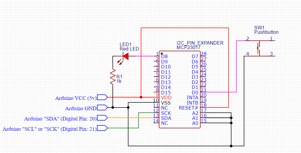
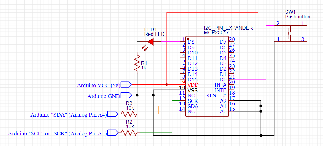
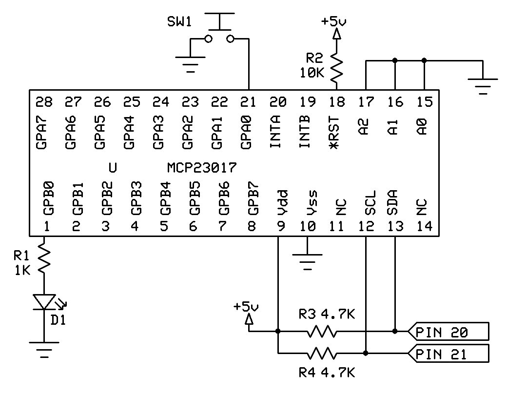
Here is my code (I combined it with a pushbutton-activated mode switching sketch to turn on or off an LED. It has the same wiring as the code @groundFungus supplied):

//----------------------------------------------------
#include<Wire.h>
#include<Adafruit_MCP23017.h>
Adafruit_MCP23017 mcp;

int mode = 0;

void setup() {
Serial.begin(9600);
Wire.begin();
mcp.begin();
mcp.pinMode(0,INPUT);
mcp.pullUp(0,HIGH);
mcp.pinMode(8,OUTPUT);
}

void loop() {

if(mcp.digitalRead(0) == 0){ //if the button has been pressed,
while(mcp.digitalRead(0)==0){} //loop nothing while it is being pressed
mode = mode + 1; //then add 1 mode to "mode" assuming that the button has been released (otherwise it would still be looping)
}

if(mode == 2){
mode = 0;
}
mcp.digitalWrite(8,mode);

if (mode==0){Serial.println("LOW (0v)");}
if (mode==1){Serial.println("HIGH (5v)");}
}
//----------------------------------------------------

Now, to explain:

I am so sorry, but as a new user, the forum stopped me from writing any more messages yesterday and even some of this morning. I had intended to tell everyone that all I could find was the OLD library, and the "Major Update" scrawled across the Github page made me think that Adafruit simply has not gotten to putting their new library on the manager. It said "last revision: 4 days ago" the last time I checked. I, personally, would not expect them to have the turn-around to make a change to a library and implement that change across the entire user community in just 4 days.

This is really important:

I did NOT download it directly from any website. I simply typed in the name of my MCP chip in the Library manager, found an Adafruit version (the same manufacturer as the one on the Github page), and downloaded it only from the Libraries Manager with no websites directly being used to aquire that specific library.

HOWEVER: I did use the same functions (along with the functions @groundFungus suggested) as the new library because I knew that it would not be very optimal for Adafruit if they had 2 seperate libraries. Because of this, I knew that the "Adafruit_MCP23017" library may terminate at any time. That is why, when or if the new version is available on the manager, (because we used the same functions), it should be able to work with the new library.

Just wanted to say thank you so much to @Koepel for the I2C scanner (helpful when using multiple I2C devices), @Grumpy_Mike for showing me how to wire a pushbutton with only 2 pins, and a special thanks to @groundFungus for the wiring of the chip as well as helping with details in the code (such as finding out that INPUT_PULLUP does not work).

Before clicking the "Solution" box, would it be ok if I were to type up a summary of what I found to be helpful in getting this chip to work?

That is up to you. This forum is not so strict. I think that groundFungus showed well enough how to use it.

You did the right thing by using the Library Manager, it is Adafruit that messed up.
All I wanted to do is to compare your code with an example of the library that you use. Therefor I wanted to know exactly which library you use. Sometimes I spend my time looking at the wrong library.
Some website have their own "special" version of a library. Some people even download a copy of the Arduino IDE from a questionable website :astonished:

I would say, yes please.

One thing that I want to mention is that my schematic shows no pullup resistors on the I2C pins. That is because the Mega board has 10K pullup resistors on the I2C bus. Other boards may not have those pullups (internal pullups are usually not strong enough). If used with an Uno or Nano, for instance, the chip will need to have external pullups installed. 4.7K is the oft recommended value.

Oh, ok. Thank you! I did not know that.

That would explain how some diagrams show pull-up resistors and some don't.

I may spend a bit of time to make sure that I can sum up things as best I can before clicking the solution box.

A special thank you to all.

njmaas55

Hello!

For those who just skipped right to the end, I hope you find your efforts fruitful.
This is a summary of what I have learned and what I think would help others who also are having troubles with the MCP23017 pin expander.

//----------------------------------------------------------------

Things to do:

  1. Always run an I2C Scanner before you test a new wiring setup to check that your board is able to communicate on the I2C bus well. If successful, move on to the next step. If not, follow this wiring diagram for the Arduino Mega:

Below is the wiring diagram for almost any other board:

//----------------------------------------------------------------

  1. Download the Adafruit library "Adafruit_MCP23017" via the Library Manager (officially known as the "Manage Libraries..." icon in the "Tools" dropdown menu of the Arduino IDE).

//----------------------------------------------------------------

  1. Copy or modify the given code:

     #include<Wire.h>               //I2C library
     #include<Adafruit_MCP23017.h>  //MCP23017 chip library
     Adafruit_MCP23017 mcp;         //create an object for the MCP library
     
     int mode = 0;                  //create an int named "mode" that is equal to 0
     
     void setup() {
       Serial.begin(9600);          //wake up Serial Monitor
       Wire.begin();                //wake up I2C library
       mcp.begin();                 //wake up MCP23017 chip
       mcp.pinMode(0,INPUT);        //set pin 0 to be an input  (connected to button)
       mcp.pullUp(0,HIGH);          //set pin 0 to activate its internal pull-up resistor
       mcp.pinMode(8,OUTPUT);       //set pin 8 to be an output (connected to LED)
     }
     
     void loop() {
    
       if(mcp.digitalRead(0) == 0){      //if the button has been pressed,
         while(mcp.digitalRead(0)==0){}  //loop nothing while it is being pressed
       mode = mode + 1;                  //then add 1 mode to "mode" assuming that the button has been released (otherwise it would still be looping)
       }
    
       if(mode == 2){                    //if the button has been pressed twice,
         mode = 0;                       //reset "mode" to equal 0 again
       }
       mcp.digitalWrite(8,mode);         //digitalWrite either a 1 or 0 to pin 8 (connected to LED)
    
       if (mode==0){Serial.println("LOW  (0v)");}   //if mode = 0, print "LOW  (0v)" on the screen
       if (mode==1){Serial.println("HIGH (5v)");}   //if mode = 1, print "HIGH (5v)" on the screen
     }
    

//----------------------------------------------------------------

Things to Know While Remixing this Code:

  • All of the functions a basic user would need in his/her code are addressed as their normal name, but with "mcp." as a prefix. This includes all of its supported functions. When you want the MCP23017 to execute a function or task, type in "mcp." and then the function you want to call in its normal placing in either in the void setup, void loop, or even in your own void function or "non-void" function. If the function cannot be used on the MCP23017 chip such as analogRead, an error message will tell you that " 'class Adafruit_MCP23017' has no member named 'analogRead'"

  • The MCP23017 pin expander is a DIGITAL ONLY device. This means that it can only use digital functions (example: digitalWrite, digitalRead, a home-made version of the Servo library, etc.), but it cannot read analog signals (example: analogRead, analogWrite, etc.).

  • While you can sometimes get away with not declaring "pinMode()" on Arduino boards, it is required to set the pinMode of the pins you will be using on the MCP23017.

  • Calling "mcp.pinMode(pin number, INPUT_PULLUP);" does not work. Instead, it is required that the pull-up resistor is activated by calling:

    mcp.pinMode(pinNumber,INPUT);        //set the pin that you want to address in place of "pinNumber" to be an input
    mcp.pullUp(pinNumber,HIGH);          //set the pin that you want to address in place of "pinNumber" to activate its internal pull-up resistor 
    

    This will also activate the internal pull-up resistor on that pin. You delcare this code in the same place as where you would normally declare pinMode.

//----------------------------------------------------------------

I hope that this summary has allowed you to better understand the MCP23017 pin expander. The other contributers in this chat helped me to save massive amounts of time by allowing their knowledge to be distributed on this website quickly and efficently. If you have any other questions, feel free to start a new discussion about any details I may have missed. Hopefully, I, along with the other members of this topic can come to your aid.

njmaas55

2 Likes

Sorry, but your second schematic is not quite right. The pullup resistors on SDA and SCL go from those pins to Vcc, not in series and the recommended value is 4.7K.

There is a newer version of the library (as pointed out by @ Koepel). That version may be different (pinMode might work, for instance) so be aware.

Other than that the write up should be helpful and thanks for taking the time. Not many members do. It is appreciated.

1 Like

There is a lot more to this chip that that. For example the two interrupts pins can detect a change in any input pins you want. You don't have to connect this pin to an Arduino interrupt pin, just a normal input pin will do. Then all your code has to do is to monitor this pin, which is quick, then only read the MCP23017 (which is slow) when you know something has changed and you want to see what.

For fast signals the input is latched when the interrupt has been generated so you know the state of the pins if something changed after the interrupt was generated. These is also a register to invert the input of selected lines. That can be useful in some circumstances but cosmetically can be used by beginners who expect to see a HIGH signal when a button is pressed, not the zero that a correctly wired switch returns.

Finally there is a MCP23S17, which has the same innards but is read using the SPI protocol. This can be up to 10 to 20 times faster than the I2C bus.

1 Like

This topic was automatically closed 120 days after the last reply. New replies are no longer allowed.