Problem with an I2C Pin Expander

Hello!

I have recently bought 6 MCP23017 pin expanders. They use the I2C bus, which I am not familiar with. I have only wired an MPU6050, and that worked fine, so I thought that I had the confidence to buy a second set of I2C devices.

After a few days of trying to get these pin expanders working on an Arduino Mega, I cannot seem to reach my goal. Specifically, my goal is to print a set of 1's and 0's while a button is being pressed and released using the MCP23017's internal pullup resistors. All that occurs is I get a string of 0's even though a button is supposed to return 1 while not being pressed in this configuration. Lighting up an LED also does nothing. It remains dark.

I have wired the pushbutton so that the left leg is connected to a 10k ohm resistor and the right leg is connected to pin 1 of the MCP23017 (GPB0).

I have connected pin 12 of the chip (SCL) to pin 21 on the Arduino Mega, and pin 13 of the MCP (SDA) to 20 of the Mega.

The MCP's pin 9 (VDD) was connected to 5v, and pin 10 (VSS) was connected to GND.

Pins 15, 16, and 17 (A0, A1, A2) were connected together and then wired to GND.

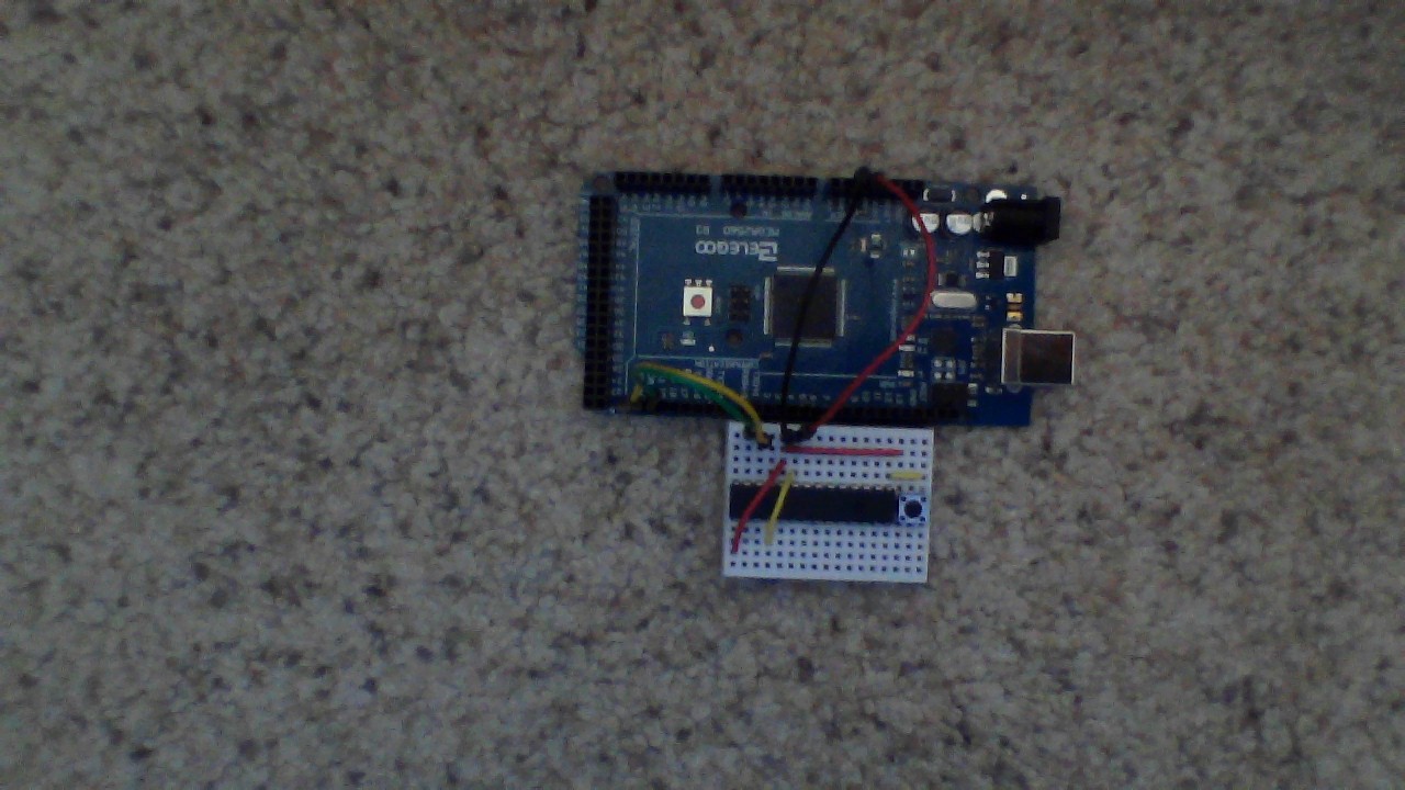
I have tried to link a photo of my wiring in this post, and I hope that it will show all of the deltails that I have described above with more ease.

(Please note that, though not shown in the image, there are small wires connecting A0, A1, and A2)

My code is as follows:
//----------------------------------------------
#include <Wire.h>
#include <Adafruit_MCP23017.h>
Adafruit_MCP23017 mcp;

void setup() {
Serial.begin(9600);
Wire.begin();
mcp.begin();
mcp.pinMode(0,INPUT_PULLUP);
}

void loop() {

Serial.println(mcp.digitalRead(0));
}
//----------------------------------------------

Based on looking around on varoius different electronics websites, pin 1 is addressed as "0" in the code because of its formal name: "GPB0"

In addition to everything stated before, I would like to note that I have also tried wiring an LED with a 220 ohm, and then later, a 10k ohm resistor.

I am hoping that this is just a simple error on my part, and it is most likely the case. I really like the SPI bus, so I guess that I2C just isn't a thing I am good at. Hopefully, your response could change that.

Thank you for any thoughts or suggestions you may have!

Run a I2C Scanner sketch.
Once the I2C Scanner sees the chip, then you can move on.

Oh, ok...
I will do that now.

The scanner ran correctly; responding 0x20 as the address. Though when I tried running the code again, it still replied only 0's.

Which library do you use ? Where can I find it and how did you install it.

Which is not the way to wire up push buttons. You need to wire the button between input and ground. Then you code needs to call up the input pull up resistors in your chip.
Then pushing the button will read a zero, releasing it will input a high or logic one.

As you have it your inputs are floating when not pushed.

As for Koepel, I am using the Adafruit_MCP23017 library.

Hopefully to answer Grumpy_Mike, I believe that I should have specified that the 10k resistor is linked to GND, and that other leg was connected to the input with the internal pullup. On a normal digital pin, this seems to work for me.

This is the code I used to verify this, and it may just be my bad job at explaining my wiring. A picture is worth a thousand words...
//---------------------------
void setup() {
// put your setup code here, to run once:
Serial.begin(9600);
pinMode(2,INPUT_PULLUP);
}

void loop() {
// put your main code here, to run repeatedly:
Serial.println(digitalRead(2));
}
//-----------------------------------------------

Just to help Koepel a bit more, here is a link to the Github page for the Library

My code is an adapted and shortened version of the button example on the Github page. Now to think of it, it may be that shortening process that I slipped up on. I also used the help from this video: How to connect the MCP23017 GPIO Expander to an Arduino and Raspberry Pi - YouTube

I once slipped up shortening code in that it happened to me earlier this year with my nrf24l01 tranciever chip, in that I forgot to clear the RX buffer and it glitched when I tried to call "!radio.available();" because it would read the 4 good messages in the buffer and it would always return saying that it was still recieving information, even though it was only reading the old messages in the buffer. Guess what fixed that? One line of code. "radio.flush_RX;" That got rid of the old information, so that it could read, store, and then delete only 1 message at a time.

Grumy_Mike!

I believe I now know what you were asking of me!
I tried to wire the pushbutton so that there was no resistor like this:

Like you were saying, the button is between the input and GND. The internal pullup resistor takes care of getting rid of the floating numbers.

And just like you said, it read 0's while pressed, and 1's while released.

Thank you!

I will now try it with the MCP23017 chip.

I have rewired the MCP23017 chip, and even after running the I2C scanner with no glitches with that code, it still returns the same column of 0's even while released.

Maybe you need a 4.7K ohm pull-up resistor on SDA, pin13?

Ok, I will try that!
Thank you!

Though I have seen wiring diagrams that use 4.7k ohm all the way up to 10k ohm pull-up resistors on their SDA and/or SCL lines, it did not seem to work for me. It still responds with the row of 0's on the Serial Monitor.

I wired up a MCP23017 chip to my Mega with a switch connected to the MCP pin GPA0 (physical pin 21). The rest of the wiring should match the description in the OP. The switch is wired one side to ground and the other to the input. I tried the OP code and it did not work. I changed the pinMode to match the Adafruit_MCP23017 library button example and that code did work. Here i have introduced blink wihout delay timing to slow down the serial output and added the on board LED (pin 13) to follow the switch state. This displays 1 in serial monitor for an unpressed switch and 0 for the pressed switch.

#include <Wire.h>
#include <Adafruit_MCP23017.h>
Adafruit_MCP23017 mcp;

const byte ledPin = 13;
const byte switchPin = 0;

void setup()
{
   Serial.begin(9600);
   Wire.begin();
   mcp.begin();
   //mcp.pinMode(0, INPUT_PULLUP); // apparently INPUT_PULLUP does not work.
   mcp.pinMode(switchPin, INPUT);
   mcp.pullUp(switchPin, HIGH);
   pinMode(ledPin, OUTPUT);
}

void loop()
{
   static unsigned long timer = 0;
   unsigned long interval = 200;
   if (millis() - timer >= interval)
   {
      timer = millis();
      bool switchState = mcp.digitalRead(switchPin);
      digitalWrite(ledPin, switchState);
      Serial.println(switchState);
   }
}

Not that the code is formatted with the IDE autoformat tool (ctrl-t or Tools, Auto Format) and posted in code tags. See the forum guidelines.

This code looks great!!!
It looks like I can see two things:

  1. My wiring of the button may be incorrect
  2. INPUT_PULLUP may have been my second problem.

Would it be possible to show your wiring?
Here is mine:

Here is my wiring. I added a LED to GPB0 (IDE pin 8 or physical pin 1) that follows the switch state (like pin 13). Sorry, I misread the OP in that I thought the switch was on GPA0 instead of GPB0. The code had pin 0 which is GPA0 (GPB0 is pin 8). See the pin addressing here.

Code with LED.

#include <Wire.h>
#include <Adafruit_MCP23017.h>
Adafruit_MCP23017 mcp;

const byte ledPin = 13;
const byte switchPin = 0;
const byte led_2Pin = 8;

void setup()
{
   Serial.begin(9600);
   Wire.begin();
   mcp.begin();
   //mcp.pinMode(0, INPUT_PULLUP); // apparently INPUT_PULLUP does not work.
   mcp.pinMode(switchPin, INPUT);
   mcp.pullUp(switchPin, HIGH);
   pinMode(ledPin, OUTPUT);
   mcp.pinMode(led_2Pin, OUTPUT);
}

void loop()
{
   static unsigned long timer = 0;
   unsigned long interval = 200;
   if (millis() - timer >= interval)
   {
      timer = millis();
      bool switchState = mcp.digitalRead(switchPin);
      digitalWrite(ledPin, switchState);
      mcp.digitalWrite(led_2Pin, switchState);
      Serial.println(switchState);
   }
}

So where is the "Adafruit_MCP23017.h" coming from ? I can not find it in the link you gave.

I don't know and you are right. If you go to the library manager and find the Adafruit_MCP230217 library, that link is where the more info button sends you. But the Adafruit_MCP23017.h file is installed with the library.

@groundFungus, I know, but I wanted @njmaas55 to tell me that in case it is a very old version with a bug downloaded from a bad website.

Adafruit changed the library and messed up. The Library Manager installs the old version, but the old version is no longer at Adafruit's Github.