Hi, I have a problem with gy906 IR sensor.
It’s the 3.3V model but my arduino nano didn’t see it at all.
I tried everythings, changed ports and also.
Anyone can help me?
Welcome to the forum
Please clarify exactly which Nano board you have. Is it the classic board or a later version with a similar name ?
How is the sensor connected to the Nano and powered
Hi, @alby23mod
Can you post a link to data/specs/where you purchased the sensor.
Most modules are 5V with a 3V3 regulator.
Thanks.. Tom.. ![]()
![]()
![]()
![]()
I bought this:
I connected this to 3V pin, GND, A5 and A4
Classic board, I used it before and also if I use a 16X2 LCD i2C it works
Hi,
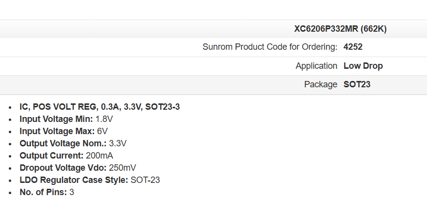
Can you tell us what is written on the circled component?


I got to get some of these, 1TB and 1GHz speed.

Your module may have a 5 to 3v3 regulator.
Thanks.. Tom... ![]()
![]()
![]()
![]()
The code is:662k
Pls help me I have to use it for a university project ![]()
Update: I tried to use it with 5V but it doesn’t work
Write a minimal sketch to just read the sensor and print the results and post it here with a schematic showing all components and how they are connected and powered
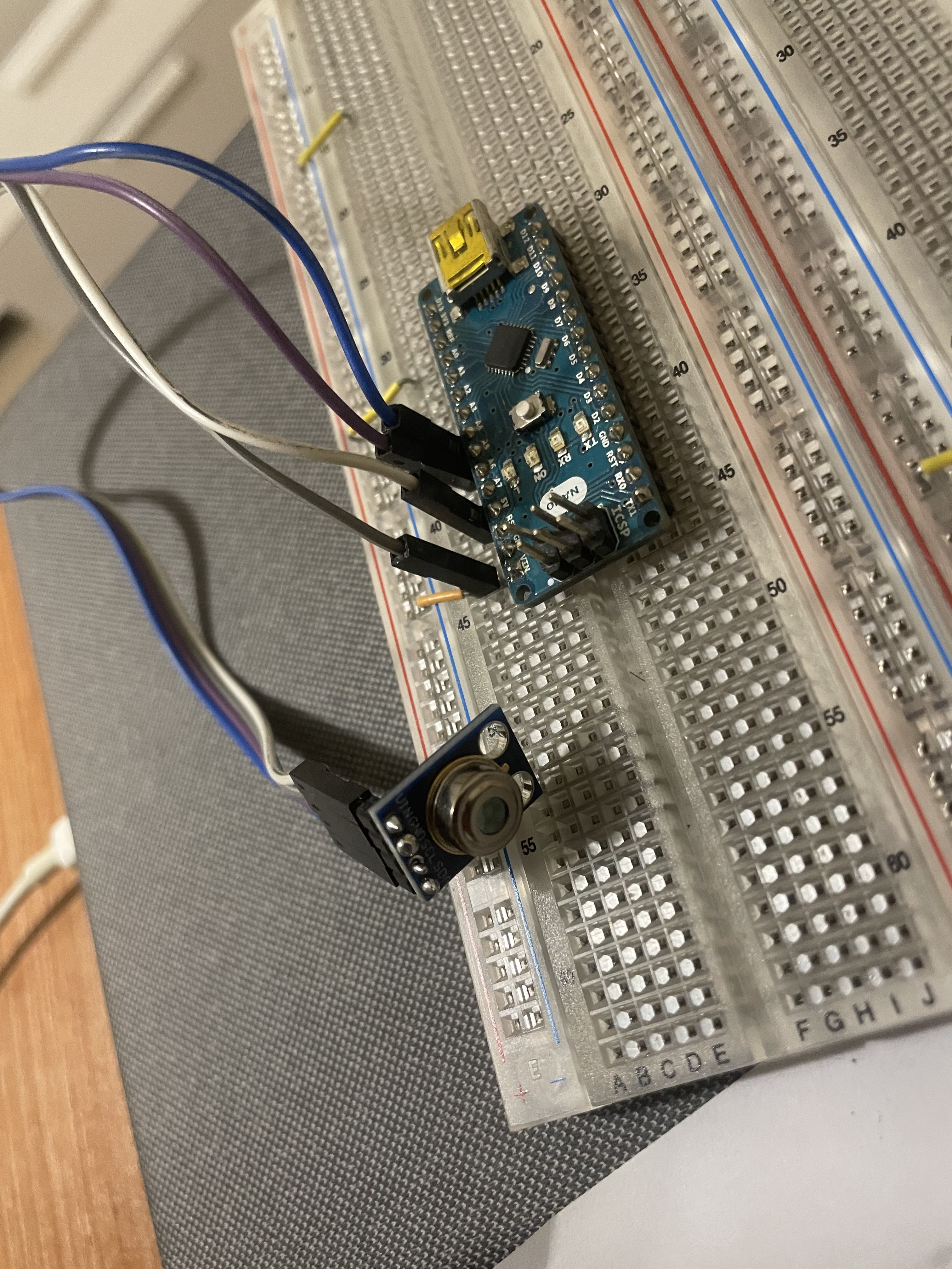
It is difficult/impossible to see which pins the wires are connected to on both ends
Vin-->5V
GND-->GND
SCL-->A5
SDA-->A4
I tried also 4 sensor and used a raspberry also.
can be a problem of scan i2c frequency?
Hi alby23mod,
please post your code.
You are right, the i2c clock normally needs to be limited to 100kHz for this sensor.
*
 * See app note:
 * https://www.melexis.com/en/documents/documentation/application-notes/application-note-mlx90614-changing-emissivity-setting
 *
 * 1. Write 0x0000 to address 0x04 (erase the EEPROM cell)
 * 2. Write the new value to address 0x04
 * 3. Read the value in address 0x04 in order to check that the correct value is stored
 * 4. Restart the module
 *
 */

#include <Adafruit_MLX90614.h>

//== CHANGE THIS ============
double new_emissivity = 0.95;
//===========================

Adafruit_MLX90614 mlx = Adafruit_MLX90614();

void setup() {
  Serial.begin(9600);
  while (!Serial);

  Serial.println("Adafruit MLX90614 Emissivity Setter.\n");

  // init sensor
  if (!mlx.begin()) {
    Serial.println("Error connecting to MLX sensor. Check wiring.");
    while (1);
  };

  // read current emissivity
  Serial.print("Current emissivity = "); Serial.println(mlx.readEmissivity());

  // set new emissivity
  Serial.print("Setting emissivity = "); Serial.println(new_emissivity);
  mlx.writeEmissivity(new_emissivity); // this does the 0x0000 erase write

  // read back
  Serial.print("New emissivity = "); Serial.println(mlx.readEmissivity());

  // done
  Serial.print("DONE. Restart the module.");
}

void loop() {
}
Ok.
What is the outcome of starting this code? Wat is reportet with serial out?
What is the expected result?
It say something like “sensor not detected, check wire”
It would show the temp but it doesn’t dected sensor
"Error connecting to MLX sensor. Check wiring."
is indeed indicating, that the sensor is not reacting properly on the trial to initialize it by the lib.
Beside of that, you code example wouldn´t show the temperature. You sample code recalibrate the sensor with an manual edited value. Better not to bring this really to run. It would destroy the probably reasonable calibration.
Can you please the try this i2c scan example:
#include "Wire.h"

void setup() {
  Serial.begin(115200);
  Wire.begin();
}

void loop() {
  byte error, address;
  int nDevices = 0;

  delay(5000);

  Serial.println("Scanning for I2C devices ...");
  for (address = 0x01; address < 0x7f; address++) {
    Wire.beginTransmission(address);
    error = Wire.endTransmission();
    if (error == 0) {
      Serial.printf("I2C device found at address 0x%02X\n", address);
      nDevices++;
    } else if (error != 2) {
      Serial.printf("Error %d at address 0x%02X\n", error, address);
    }
  }
  if (nDevices == 0) {
    Serial.println("No I2C devices found");
  }
}
The sensor should be found at 0x5a.
It says no i2c device found,
I don’t know, I tried other 6 sensor like it
I am not sure about the 3,3V anf 5V business.
If you have 3,3V Sensors, this might be a problem, if the Arduino tries to communicate with 5V with them, when they are not 5V tolerant (might destroy them).
Another thing: Do you have applied pull up resistors? Can be, that this is in some combinations running without, but normally with i2c pull ups are needed:
But careful with the 5V! I am not sure, but I guess, that the sensors might be killed by that.