Hi everyone,
Its my first time here on the forum and i have a programming issue, i did my search (because i hate asking people for help) But i couldnt find notthing on the internet that could solve my problem:
Juat to make thing clear i have no trouble using my 74h595 and my 74HC165 work.
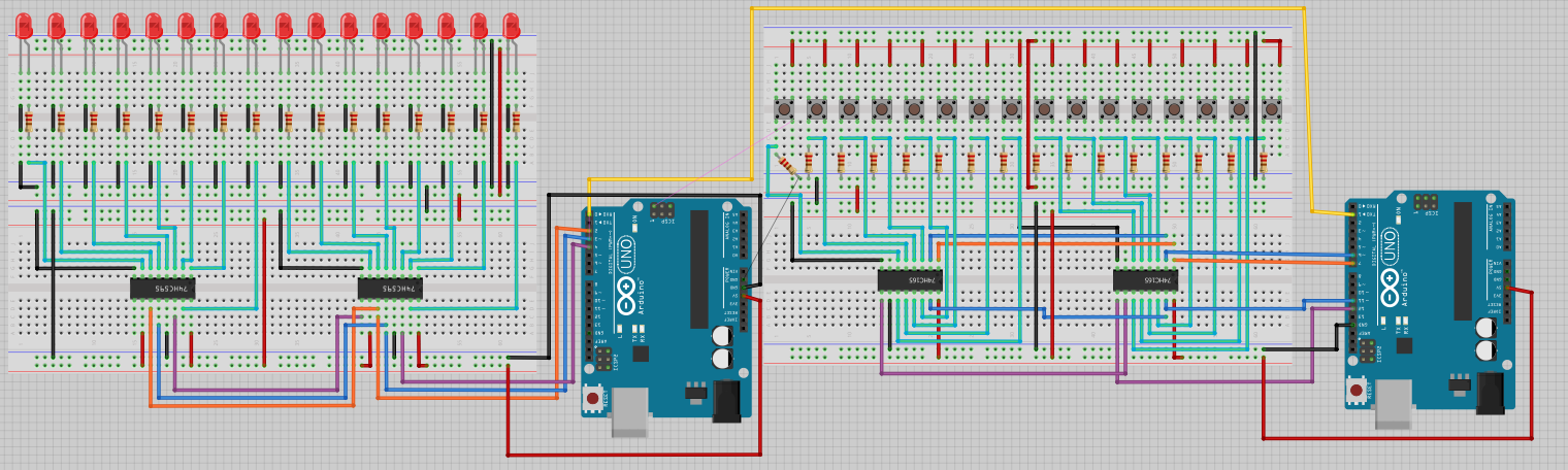
I am working on a big projet but i decided to simplify the circuits juste to make sure everything works fine.
I have to use the input data of the 74HC165 and send it to an other Arduino by serial. When he receive the data it must be able to light the good LED. Also if more than one swiches are pressed , then the equivalents LED must be turned on (ok no there is nothing wrong with turning LED on =P ).
Here is the code of the first arduino (the one with the Switches) :
/* How many shift register chips are daisy-chained.
*/
#define NUMBER_OF_SHIFT_CHIPS   2

/* Width of data (how many ext lines).
*/
#define DATA_WIDTH   NUMBER_OF_SHIFT_CHIPS * 8

/* Width of pulse to trigger the shift register to read and latch.
*/
#define PULSE_WIDTH_USEC   5

/* Optional delay between shift register reads.
*/
#define POLL_DELAY_MSEC   1

/* You will need to change the "int" to "long" If the
 * NUMBER_OF_SHIFT_CHIPS is higher than 2.
*/
#define BYTES_VAL_T unsigned int

int ploadPin        = 8;  // Connects to Parallel load pin the 165
int clockEnablePin  = 9;  // Connects to Clock Enable pin the 165
int dataPin         = 11; // Connects to the Q7 pin the 165
int clockPin        = 12; // Connects to the Clock pin the 165

BYTES_VAL_T pinValues;
BYTES_VAL_T oldPinValues;

/* This function is essentially a "shift-in" routine reading the
 * serial Data from the shift register chips and representing
 * the state of those pins in an unsigned integer (or long).
*/
BYTES_VAL_T read_shift_regs()
{
    byte bitVal;
    BYTES_VAL_T bytesVal = 0;

    /* Trigger a parallel Load to latch the state of the data lines,
    */
    digitalWrite(clockEnablePin, HIGH);
    digitalWrite(ploadPin, LOW);
    delayMicroseconds(PULSE_WIDTH_USEC);
    digitalWrite(ploadPin, HIGH);
    digitalWrite(clockEnablePin, LOW);

    /* Loop to read each bit value from the serial out line
     * of the SN74HC165N.
    */
    for(int i = 0; i < DATA_WIDTH; i++)
    {
        bitVal = digitalRead(dataPin);

        /* Set the corresponding bit in bytesVal.
        */
        bytesVal |= (bitVal << ((DATA_WIDTH-1) - i));

        /* Pulse the Clock (rising edge shifts the next bit).
        */
        digitalWrite(clockPin, HIGH);
        delayMicroseconds(PULSE_WIDTH_USEC);
        digitalWrite(clockPin, LOW);
    }

    return(bytesVal);
}

/* Dump the list of zones along with their current status.
*/
void display_pin_values()
{
    for(int i = 0; i < DATA_WIDTH; i++)
    {
        if((pinValues >> i) & 1)
            Serial.print("1");
        else
            Serial.print("0");
    }

    Serial.print("\r\n");
}

void setup()
{
    Serial.begin(9600);

    /* Initialize our digital pins...
    */
    pinMode(ploadPin, OUTPUT);
    pinMode(clockEnablePin, OUTPUT);
    pinMode(clockPin, OUTPUT);
    pinMode(dataPin, INPUT);

    digitalWrite(clockPin, LOW);
    digitalWrite(ploadPin, HIGH);

    /* Read in and display the pin states at startup.
    */
    pinValues = read_shift_regs();
    display_pin_values();
    oldPinValues = pinValues;
}

void loop()
{
    /* Read the state of all zones.
    */
    pinValues = read_shift_regs();

    /* If there was a chage in state, display which ones changed.
    */
    if(pinValues != oldPinValues)
    {
        display_pin_values();
        oldPinValues = pinValues;
    }

    delay(POLL_DELAY_MSEC);
}
On the serial it looks like this:
1000000000000000
0000101010000011
0000000000000001
This is not binary (well i guess) , each 1 represents a switch that is pressed. The numbers are in order of the switches and there is 16 numbers.
And here is the code of the second arduino (Yes the is just 8 LED for this one and it is not meant to receive data in the format of 10001010101010).
I want him to take the data from the serial and to convert it into a simple number in order to light the good LED..
int SER_Pin = 2;
int RCLK_Pin = 3;
int SRCLK_Pin = 4;

//How many of the shift registers - change this
#define number_of_74hc595s 1

//do not touch
#define numOfRegisterPins number_of_74hc595s * 8

boolean registers[numOfRegisterPins];

void setup(){
  pinMode(SER_Pin, OUTPUT);
  pinMode(RCLK_Pin, OUTPUT);
  pinMode(SRCLK_Pin, OUTPUT);

  Serial.begin(9600);
  //reset all register pins
  clearRegisters();
  writeRegisters();
}

//set all register pins to LOW
void clearRegisters(){
  for(int i = numOfRegisterPins - 1; i >=  0; i--){
     registers[i] = LOW;
  }
}

//Set and display registers
//Only call AFTER all values are set how you would like (slow otherwise)
void writeRegisters(){

  digitalWrite(RCLK_Pin, LOW);

  for(int i = numOfRegisterPins - 1; i >=  0; i--){
    digitalWrite(SRCLK_Pin, LOW);

    int val = registers[i];

    digitalWrite(SER_Pin, val);
    digitalWrite(SRCLK_Pin, HIGH);

  }
  digitalWrite(RCLK_Pin, HIGH);

}

//set an individual pin HIGH or LOW
void setRegisterPin(int index, int value){
  registers[index] = value;
}

void loop(){

  if (Serial.available() > 0) {
    // get incoming byte:
    int inByte = Serial.read();

//Relay 1
  if (inByte == 1) {
      // turn LED on:
      setRegisterPin(1, HIGH);
      writeRegisters();
    }
    else {
      // turn LED off:
      setRegisterPin(1, LOW);
      writeRegisters();
    }

//Relay 2
  if (inByte == 2) {
      // turn LED on:
      setRegisterPin(2, HIGH);
      writeRegisters();
    }
    else {
      // turn LED off:
      setRegisterPin(2, LOW);
      writeRegisters();
    }

//Relay 3
  if (inByte == 3) {
      // turn LED on:
      setRegisterPin(3, HIGH);
      writeRegisters();
    }
    else {
      // turn LED off:
      setRegisterPin(3, LOW);
      writeRegisters();
    }

//Relay 4
  if (inByte == 4) {
      // turn LED on:
      setRegisterPin(4, HIGH);
      writeRegisters();
    }
    else {
      // turn LED off:
      setRegisterPin(4, LOW);
      writeRegisters();
    }

//Relay 5
  if (inByte == 5) {
      // turn LED on:
      setRegisterPin(5, HIGH);
      writeRegisters();
    }
    else {
      // turn LED off:
      setRegisterPin(5, LOW);
      writeRegisters();
    }

//Relay 6
  if (inByte == 6) {
      // turn LED on:
      setRegisterPin(6, HIGH);
      writeRegisters();
    }
    else {
      // turn LED off:
      setRegisterPin(6, LOW);
      writeRegisters();
    }

//Relay 7
  if (inByte == 7) {
      // turn LED on:
      setRegisterPin(7, HIGH);
      writeRegisters();
    }
    else {
      // turn LED off:
      setRegisterPin(7, LOW);
      writeRegisters();
    }

//Relay 8
  if (inByte == 8) {
      // turn LED on:
      setRegisterPin(8, HIGH);
      writeRegisters();
    }
    else {
      // turn LED off:
      setRegisterPin(8, LOW);
      writeRegisters();
    }
  }
}
Can someone please help me, i search like crazy to find a solution but i couldnt find one....did i miss something? I'm not an expert in Arduino! Thanks!! ![]()
PS:The wiring on the breabords view may not represent the values on the code, but its just to illustrate my setup