Thank you! I’ll follow the diagram and hopefully my LCD will work!
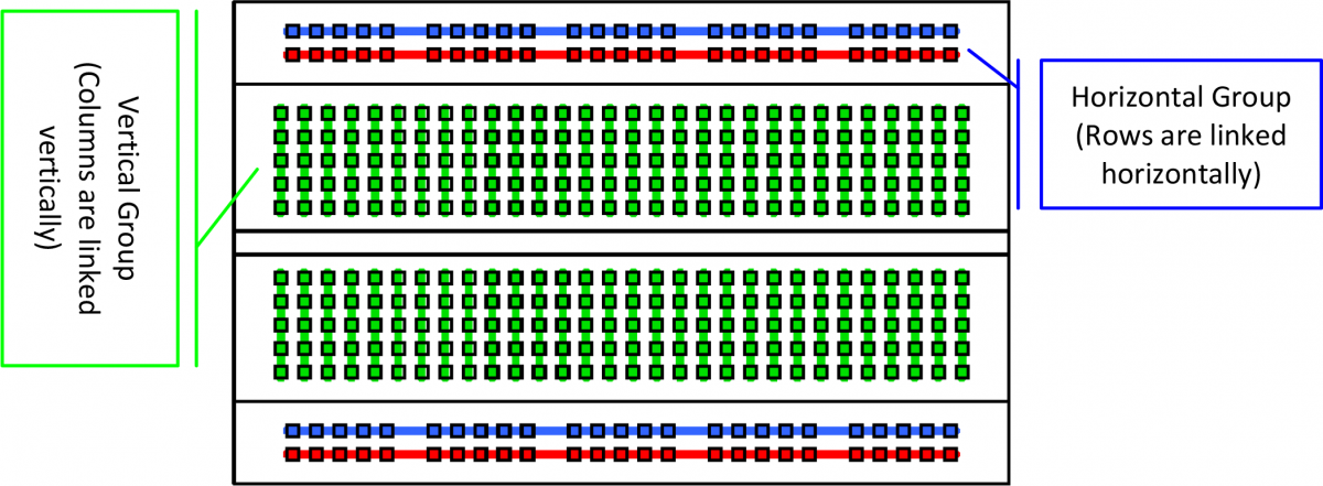
The red and blue rails holes are all connected horizontally
(Source)
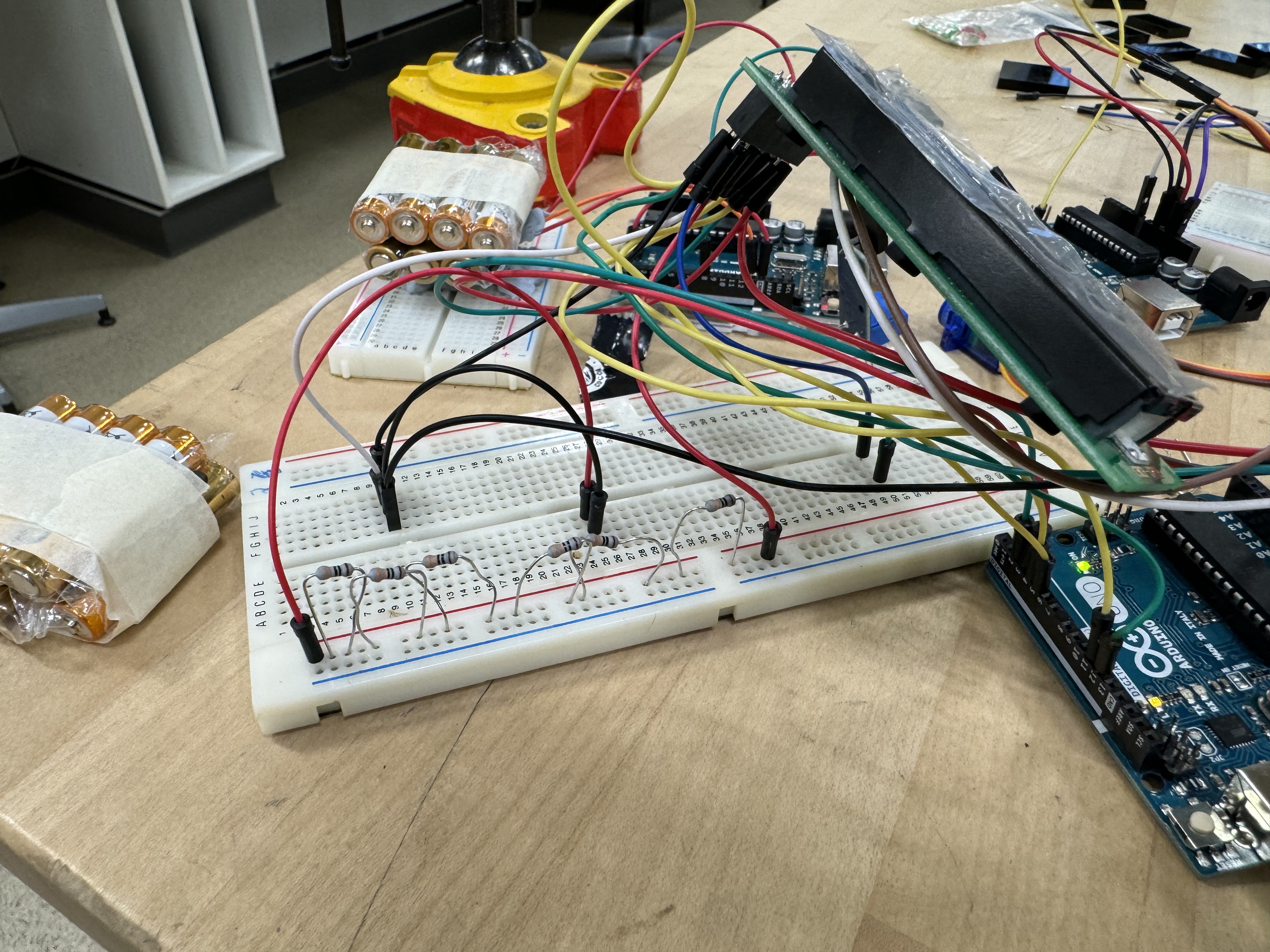
Your resistors are in the wrong place
Be careful with the power and ground rails on that bread board.
It appears that you have a bread board with separate rails.
Look a the red and blue lines.
There is a break in the middle. That usually means that the two sides are isolated from each other
If you have separate rails and want to use both sides (as you have shown in your recent photos) you must put a wire that connects between the two sides.
--- bill
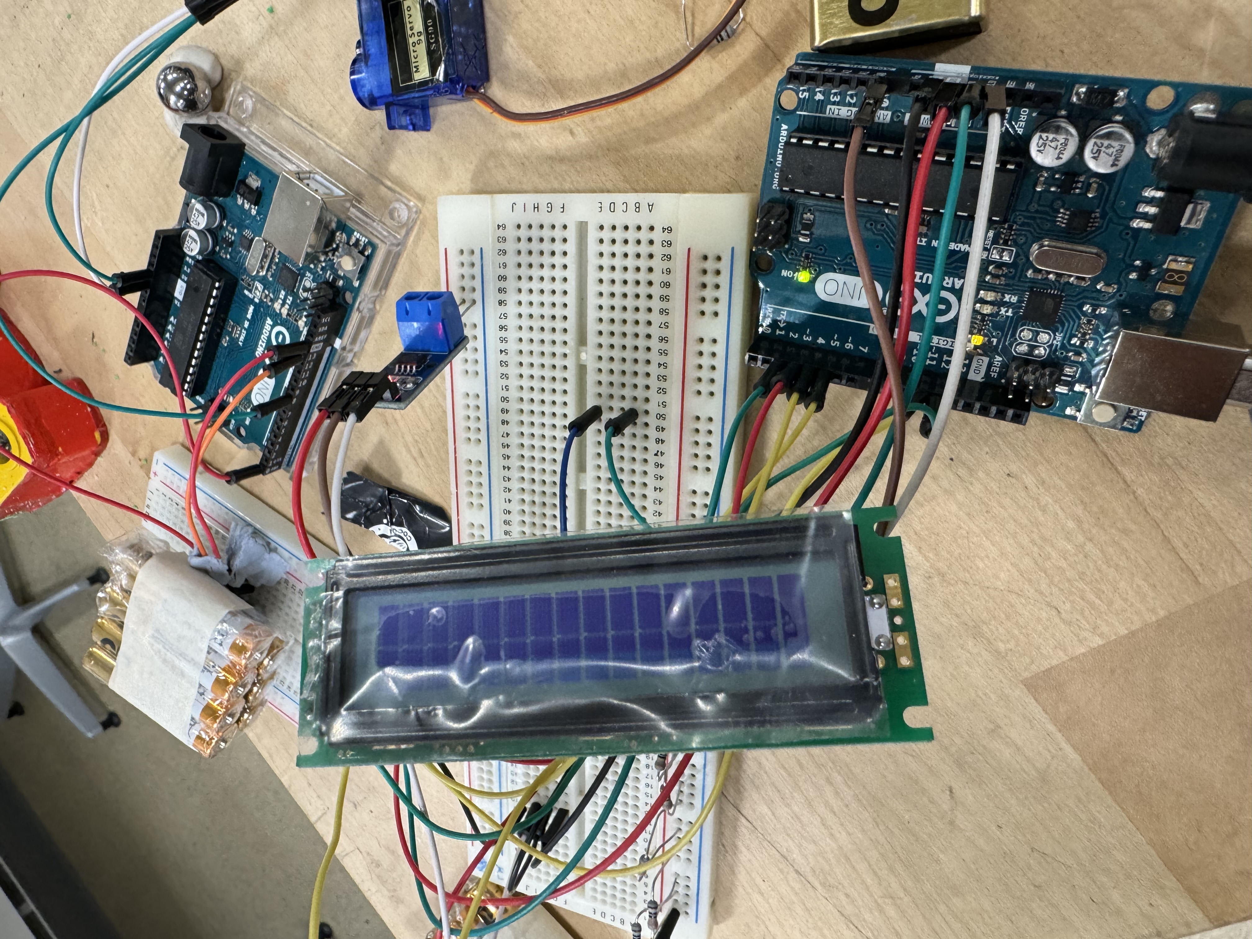
Why are there so many resistors on the breadboard of post #22? For R1 of Fig-1 of post #20, place around a 2k ohm resistor and the same value for R2. Make one jumper connection between LCD and UNO.
First of all check that your LCD is working for which you disconnect all other modules from the UNO. Once LCD is found working, then connect other modules/circuits/sensors one at a time.
This topic was automatically closed 180 days after the last reply. New replies are no longer allowed.